Indice Index indeks. La Compañia The Company Şirketimiz 04. Soluciones Solutions Çözümlerimiz 12. Notas Técnicas Papers Ürünlerimiz 20
|
|
|
- Emine Erkoç
- 8 yıl önce
- İzleme sayısı:
Transkript
1

2 Indice Index indeks 01 La Compañia The Company Şirketimiz 04 Consultoría en sistemas de potencia Power system consulting Güç sistemleri danışmanlık hizmetleri 06 Soluciones de vanguardia Leading edge solutions İleri düzey çözümler 08 Soporte global Global Support Uluslar arası destek Soluciones Solutions Çözümlerimiz 12 Estudios por simulación Simulation Studies Simülasyon Çalışmaları 14 Ensayos en terreno Field testing Saha Testleri 16 I+D Software y Hardware R&D Software & Hardware AR-GE Yazılım ve Donanım 18 Notas Técnicas Papers Ürünlerimiz 20 Hardware Saturn FK Software PlotCapability On-Line 28 Load Manager (v1.0) 34 Photon Experiancia global Global Experience Global Deneyim 60
 34 Photon 3.")
3 La Compañia The Company Şirketimiz 01
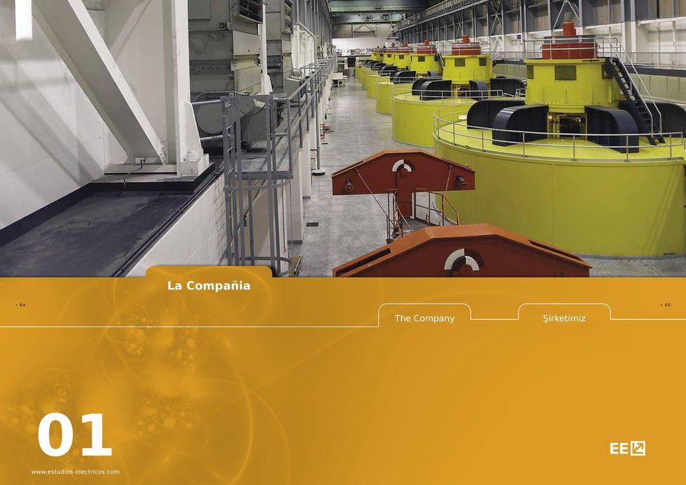
4 06 01 La Compañia The Company Şirketimiz 07 Consultoría en sistemas de potencia Power system consulting Güç sistemleri danışmanlık hizmetleri Somos un centro de especialistas en sistemas de potencia que responde con soluciones concretas de ingeniería a las necesidades específicas de los diferentes agentes del mercado eléctrico global. We are a group of power system specialists responding to specific engineering solutions as well as the needs of the different agents in the global electricity market. Güç sistemleri alanında uzmanlaşmış olan firmamız, uluslar arası alanda elektrik piyasaları katılımcılarınının gereksinimleri doğrultusunda özel mühendislik hizmetleri sunmaktadır. En Estudios Eléctricos asumimos cada desafío, porque es nuestra manera de llegar a una solución inmediata, real y a medida. El diagnóstico preciso y la respuesta a tiempo es nuestro principal objetivo. Estudios Eléctricos assume every challenge because it s our way of reaching an immediate and real solution. The accurate diagnosis and time response is our main objective. EE, doğru çözüme süratle ulaşmak için, uygulamada karşılaşabileceği sorunları önceden hesaba katarak çalışmayı usül kabul etmiştir. Hedefimiz, optimum çözümü en kısa sürede sunmaktır. Diariamente nos planteamos la tarea de atender inmediatamente los problemas de nuestros clientes porque sabemos y entendemos la criticidad de estos procesos y los requerimientos del mercado. Every day we encourage ourselves on the task of immediately addressing the customers problems because we know and understand the criticality of these processes and market requirements. Prensibimiz, zamanın elektrik piyasasında ki önemini dikkate almak suretiyle, müşterilerimizin ihtiyaçlarını en çabuk şekilde karşılamaktır.

5 08 01 La Compañia The Company Şirketimiz 09 Soluciones de vanguardia Leading edge solutions İleri düzey çözümler Operamos como una plataforma dinámica, en permanente transformación y evolución, porque comprendemos las exigencias tecnológicas del mundo moderno. Nuestro grupo de R&D es el motor creativo de herramientas de última tecnología, tanto para uso interno como para el desarrollo de productos. Para nosotros esto es posible porque contamos con una estructura flexible y horizontal, conformada por ingenieros especializados y comprometidos por igual con todos los desafíos que se nos presentan. Este corpus nos posibilita minimizar los tiempos de respuesta y potenciar el nivel de nuestras soluciones. Conocimiento, know how, expertise y actitud, nos permiten brindar un servicio de excelencia. Nuestra compañía está certificada ISO en Power Plant Field Testing and Electrical Commissioning. We operate as a dynamic platform, in permanent transformation and evolution, because we understand the real technological world needs. Our group of R&D is the motor of the leading edge solutions and tools, for internal use as well as for product development. This is possible because we have a flexible and horizontal structure, integrated by engineers committed to all the challenges we face and customers success. This corpus allows us to minimize time response and enhance the level of our solutions. Knowledge, know-how, expertise and attitude allow us to deliver an excellent service. Our company is certified ISO in Power Plant Electrical Testing and Commissioning Field. Şirketimiz elektrik piyasalarındaki teknolojik gelişmelerin önemini dikkate alarak bu gelişmeleriçok yakından izlemektedir. AR-GE ekibimiz, geliştirdiğimiz ileri düzey çözümlerin temelini oluşturmakta ve bunları hem şirket içerisinde kullanmakta hem de müşteriye özel ürünler geliştirmektedir. AR-GE grubumuzun esnek ve yatay örgütlenmiş yapısı sayesinde, süreç en iyi şekilde yönetilerek müşterilerimizin başarıya ulaşması sağlanır. Yine bu yapımız sayesinde çözümlerimizin kalitesi yükseltilirken uygulamanın süreside minimize edilir. Deneyim, Know-How, uzmanlık ve sorunlara karşı göstermiş olduğumuz positif yaklaşım müşterilerimize kusursuz bir şekilde hizmet etmemizi sağlamaktadır. Şirketimiz Güç Santrallarının Elektriksel Saha Testleri ve Devreye Alma alanında ISO kalite belgesine sahiptir.

6 La Compañia The Company Şirketimiz 011 Soporte global Global Support Uluslar arası Destek La ventaja de adoptar una cultura de trabajo colaborativa y en red hace posible que nuestro equipo funcione proactivamente, asumiendo la responsabilidad conjunta de afrontar cada una de las necesidades del mundo de la energía. En nuestro Centro de Operaciones ubicado en la ciudad de Rosario, provincia de Santa Fe, Argentina supervisamos las tareas que nuestros equipos de ingenieros realizan en cualquier parte del mundo. Esta oficina funciona como el enclave físico de nuestra red y nos permite brindar respaldo logístico permanente. The advantage of adopting a collaborative work and networking culture allows our team to work proactively, responsibly to address each power plant and utility needs. In our headquarter located in Rosario city, Santa Fe, Argentina we supervise world wide operations conducted by our field engineering team. This office acts as the main location of our network which allow us to provide ongoing logistical support. Farklı kültürlerin beraber çalışmasının getirdiği avantajla ekibimiz, daha ileri düzeyde her tür de güç santralının ve endüstriyel tesisin ihtiyaç ve taleplerine cevap verecek şekilde çalışmaktadır. Arjantinin Rosariao/Santa Fe şehrinde bulunan merkezimizden dünya çapında hizmet sağlayan saha mühendislerimize destek vermekteyiz. Bütün uluslar arası projelerimizi bu merkezden yönetilmektedir.

7 Soluciones Solutions Çözümler 02
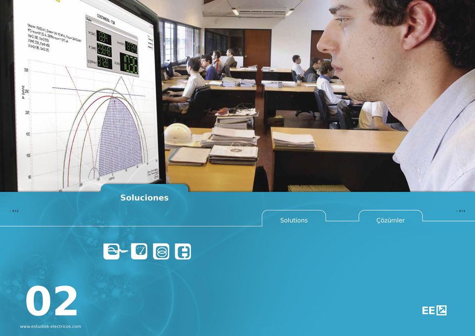
8 Soluciones Solutions Çözümler 015 Estudios por simulación Simulation Studies Simülasyon Çalışmaları Esta herramienta es la clave para el planeamiento, diseño y operación de sistemas eléctricos de potencia. Poseemos licencias legales aptas para el desarrollo de consultoría de todas las herramientas que utilizamos. Gracias a esto, los especialistas de este departamento disponemos de todos los recursos necesarios para adaptarnos a cada caso y país en particular. El desarrollo de las bases de datos estática y dinámica, junto con la experiencia en diferentes tipos de sistemas nacionales e industriales, asegura resultados óptimos en cuanto a tiempo de ejecución, conclusiones y fundamentalmente validez y aceptación de informes de los centros de despacho y organismos de control. This is the key tool for planning, design and operation of electrical power. We have legal licenses suitable for the development of consulting of the most important software used. Thanks to this, the specialists of this department have all the necessary resources to work on each case and country. The development of databases and dynamic models as well as wide range of experience in national and industrial grids ensures optimum results in terms of execution time, and fundamentally valid conclusions and acceptance of reports from dispatch centers and agencies. Güç sistemlerinin, dizaynı, planlaması ve işletmesinin en önemli aracı simülasyon çalışmalarıdır. Firmamız bu bağlamda, lisanlı olarak, dünyaca güvenilirliği kanıtlanmış yazılımları kullanmaktadır. Bu sayede mühendislerimiz ülkere ve senaryolara özel çözümler üretebilmektedir. Ayrıca uzmanlarımız ulusal ve uluslararası enterkonnekte sistemler, endüstriyel şebekeler konularında Yük Tevzi Merkezleri ve ilgili kurulmalar tarafında da kabül görmüş uluslararası geçerliliğe sahip raporlar hazırlayabilmekte, Veri Tabanı ve Dinamik Modlleri oluşturabilmektedir. Alcance general Acceso a la capacidad de Transporte. Argentina Etapas CAMMESA (PSS/E). Chile Norma Técnica (DigSILENT). Panamá (PSS/E). Centro América CRIE (PSS/E DigSILENT). Flujo de Potencia. Cortocircuitos. Estabilidad Transitoria, de Tensión, de Pequeña señal. Selectividad de Protecciones. Diseño de Sistemas de Desconexión de Carga EDAC. Diseño de Sistemas de Desconexión de Generación EDAG. Estudios de Sistema: Regulación de Frecuencia. Estabilizadores de Potencia. Transitorios Electromagnéticos. Modelado Matemático - Estudios especiales (Ad-Hoc). General scope Interconnection Studies. Argentina Stages CAMMESA (PSS/E). Chile technical standard (DigSILENT). Panamá (PSS/E). Central America CRIE (PSS/E DigSILENT. Power Flow. ShortCircuit. Transient Stability, Voltage Stability, Small Signal Stability. Selectivity Analysis. Load Schedding. Generation Schedding. Frequency Regulation. Power System Stabilizer. Electromagnectic Transient Analisys. Mathematical Modeling -Ad-Hoc studies. Hizmetlerimizin Kapsamı Enterkonnekte sistem çalışmaları. Arjantin sistem operatörü için (PSS/E). Şili sistem operatörü için (DigSILENT). Panama (PSS/E). Orta Amerika CRIE (PSS/E DigSILENT). Güç akışı. Kısa devre analizleri. Geçici hal, gerilim kararlılığı ve küçük işaret kararlılığı. Seçicilik analizleri. Yük atma. Güç atma. Frekans analizleri. Güç sistemi dengeleyicileri. Elektromanyetik geçici hal analizleri. Matematiksel modelleme ve sofistike modelleme.

9 Soluciones Solutions Çözümler 017 Ensayos en terreno Field testing Saha testleri La competitividad de los mercados eléctricos y la consecuente operación cerca de los límites de estabilidad implica que especialistas de los centros de despacho nacionales requieran de estudios con el objeto de determinar condiciones seguras. Para garantizar que las conclusiones de estos estudios sean válidas, es necesaria la utilización de modelos matemáticos cuya estructura y parametrización permitan reproducir con bastante aproximación el comportamiento real de las unidades. De esta manera, es posible mejorar la performance del sistema en su conjunto y reducir los márgenes de seguridad adoptados con la consecuente mejora económica en el despacho de unidades. En este sentido, hemos desarrollado ensayos y comisionamientos en Argentina, Chile, Perú, Guatemala, Panamá, Uruguay, Brasil, Turquía, Bélgica, Estados Unidos, Corea del Sur, Colombia, El Salvador, Costa Rica, Italia, China, Portugal. Competitive electricity markets and the subsequent operation near the limits of stability requires that specialists from the national dispach centers perform studies to determine safe conditions. To ensure that the conclusions of these studies are valid, it is necessary to use mathematical models whose structure and parameters can reproduce the actual behavior of the units. This makes it possible to improve the performance of the whole system and reduce the safety margins adopted consistent with the economic dispach of the units. In this regard, our field testing department have performed modeling and commissioning in Argentina, Chile, Peru, Guatemala, Panama, Uruguay, Brazil, Turkey, Belgium, United States, South Korea, Colombia, El Salvador, Costa Rica, Italy, China, Portugal. Gün geçtikçe daha rekabetçi hale gelen elektrik piyasaları ve bununla beraber gelişen elektrik şebekeleri, yük tevzi merkezlerini şebekenin kararlılığını sağlamak adına daha detaylı çalışmalar yapmaya itmiştir. Bunun neticesinde şebekenin güvenli bir şekilde işletilmesinin koşullarını her geçen gün yeniden tanımlamaktadırlar. Bu çalışmaların en doğru sonuçları vermeleri için, güç sisteminin gerçek tepkisi en iyi şekilde yansıtabilecek matematiksel modellerin oluşturulmalıdır. Ancak bu sayede sistemin gerçek tepkisi simüle edilebilir ve en ekonomik yük dağlımını oluşturmak için güvenli çalışma parametreleri belirlenebilir. Bu bağlamda firmamızın saha testleri departmanı, Arjanti, Şili, Peru, Guatemala, Panama, Uruguay, Brezilya, Türkiye, Belçika, ABD, Güney Kore, Kolombiya, El Salvador, Kosta Rika, İtalya, Çin ve Portekiz de santralların matematiksel modellerinin çıkartılmasında çalışmış ve elektrik ekipmanlarını devreye almışlardır. Ensayos y Comisionamiento Field Measurement and Commissioning Saha Testleri ve Devreye Alma Sistema de Control de Excitación. Limitadores de Sub y Sobre Excitación. Estabilizadores de Potencia. Sistemas de Control de Velocidad. Control Primario y Secundario de Frecuencia. Modelado de Generadores Sincrónicos. Ensayos y Coordinación de Protecciones. Medición de Aislación. Arranque en Negro. Automatic Voltage Regulator. Under and Over Excitation Limiters. Power System Stabilizer. Governor. Primary and Secondary Frequency Control. Synchronous Machine. Protections Setting and Secondary Inyection Tests. Insulation Measurement. Black Start. Otomatik Gerilim Regülatörü (AVR). Aşırı (OEL) ve Düşük (UEL) İkaz Limitleyicileri. Güç Sistemi Dengeleyicisi (PSS). Hız Regülatörü. Primer ve Sekonder Frekans Kontrolü. Senkron Makineler. Röle Kordinasyonu ve Secondary Injection. İzolasyon Ölçümleri. Toparlanma Testi (Black-Start Test)

10 Soluciones Solutions Çözümler 019 I+D Software y Hardware R&D Software & Hardware AR-GE Yazılım ve Donanım La necesidad de contar con herramientas específicas no disponibles en el mercado ha motivado la creación de nuestro departamento de I+D. Este grupo de especialistas con experiencia en ensayos en terreno, así como también en simulación de sistemas interconectados, desarrolla aplicaciones de software y hardware para uso interno, además de productos comerciales. El departamento de I+D mantiene en ejecución proyectos con objetivos inmediatos aplicaciones de apoyo a la explotación y operación de centrales de generación y de largo plazo simulador de sistemas dinámicos. The need for specific tools not available in the market motivated us to create our R&D department. This group of specialists with experience in field testing as well as in simulation of interconnected systems, develops software applications and hardware for internal use as well as commercial products. The R&D keeps running projects with immediate objectives (support applications to exploitation and operation of power generation) and long-term objectives (simulation of dynamic systems). Piyasada bulunmayan özel araçlara olan gereksinimimiz bizi AR-GE departmanını oluşturmaya yöneltti. AR-GE departmanında hem saha testlerinde hem de enterkonnte sistem simülasyonlarında deneyimli olan uzmanlar çalışmaktadır, Bu uzmanlarımız hem şirket içinde kullanım için hem de ticari maksatlı ürünler geliştirmektedirler. AR-GE departmanı geliştirdiği programlarla hem kısa vadeli hem de uzun vadeli (örneğin dinamik simülasyonlar) projelerimizi desteklemektedir. Productos de I+D R&D Products AR-GE Ürünlerimiz Simulador de Sistemas de Potencia SIMPWR. Simulador de Sistemas Dinámicos FreeSIM. Monitor On Line de Curvas de Capacidad PQ PlotCapability. Estimador de Parámetros de Control de Frecuencia SATURN FK100. Preprocesador Potencia Frecuencia PT9 Argentina. Photon: Herramienta de software para el análisis de sistema utilizando modelado y simulación. Load Manager:Software para identificar los modelos y parámetros de cargas en sistemas de potencia. Uby: Software para la determinación de parámetros del generador Power System Simulator SIMPWR. Dinamic Simulator FreeSIM. Plot Capability ON LINE. Saturn FK100 - ON LINE GOV PARAMETERS ESTIMATOR. Ad-Hoc Processor Power-Frequency. Photon: Software tool for system analisys using modelling and simulation Load Manager: Software for model and parameter identification of power system loads. Uby: Software for generator s parameter identification. Güç Sistemi Simülatörü SIMPWR. Dinamik Simülatör FreeSIM. Generatör Yüklenme Eğrisinin (PQ) On-line olarak izlenebildiği Plot Capability Online. Hız regülatörü parametrelerini online olarak oluşturan Saturn FK100. Özel amaçlı geliştirilmiş işlemci Power Frequency. Photon:Dinamik sistem simulasyonları için geliştirilmiş bir araç. Load Manager: Sistem yüklerinin modellenmesi ve parametrelerinin belirlenmesi için geliştirilmiş bir yazılımç Uby: Generatör parametrelerinin belirlenmesi için geliştirilmiş bir yazılım.

11 Notas Técnicas Papers Ürünlerimiz

12 Hardware Notas Técnicas Saturn FK 100 versión Titán El SATURN FK 100 es un instrumento que se instala en unidades generadoras con el objetivo de monitorear en tiempo real el comportamiento del regulador de velocidad frente a variaciones de la frecuencia. El objetivo: 1. Analizar la efectiva prestación de la regulación de frecuencia. 2. Optimizar el aporte y consecuentemente la operación económica de las unidades. Un completo modelo matemático interno le permite al SATURN FK 100 adaptarse a todo tipo de unidades, ya sean hidráulicas o térmicas, y a todo tipo de condiciones operativas. La solidez de los algoritmos matemáticos implementados sumado a la potencia del sistema microprocesado distribuido interno DSP, le brindan una excelente robustez y confiabilidad. Beneficios para los generadores: Las unidades que prestan el servicio de regulación de frecuencia tienen un comportamiento diferente a las que trabajan a potencia constante. Vale decir, modifican su potencia despachada en función de la frecuencia del sistema. Por ejemplo: una unidad de 50 MW operando con un estatismo del 4% que sea despachada al 95% de su máxima operable (47.5MW) agota su reserva ante una variación de frecuencia de Hz. Si la frecuencia sube a 60.3 Hz, la unidad se descarga hasta 42.5 MW, cuando en realidad sólo debería hacerlo hasta 45MW, si suponemos una reserva solicitada del 5%. Veamos ahora cómo optimizar económicamente esta operación utilizando el SATURN FK 100. Existen dos metodologías: a) Manualmente: cuando los límites de aporte comprometidos son superados, el SATURN FK 100 emitirá una alarma en la Central permitiendo al operador corregir inmediatamente esta situación, o sea al llegar a 45 MW, el operador escuchará una alarma que le indica mantener esa potencia en la unidad. b) Automáticamente: Estudios Eléctricos ha diseñado e implementado con éxito algoritmos de control que permiten este funcionamiento en forma automática. De esta manera, el SATURN FK 100 se convierte sólo en un backup controlando la operación correcta. Se puede cuantificar este beneficio? Si la frecuencia normalmente está variando alrededor de 60 Hz y suponemos que el 10% del tiempo se encuentra por encima de 60.3 Hz, situación muy probable, estaríamos ese 10% del tiempo perdiendo de vender 2.5MW/h. Esto es, suponiendo un precio de USD50 el MW/hora, la pérdida por día sería de USD300/día, con lo cual tendríamos una amortización del equipo en menos de un mes. Si las variaciones en el sistema son mayores y la frecuencia se encuentra más del 10% del tiempo por encima de su valor nominal, estos números cambian significativamente a favor del generador. Beneficios para el Sistema en su conjunto: En los mercados eléctricos competitivos, la frecuencia y la tensión son un bien que necesita ser confiable y de la mejor calidad al menor costo posible. Particularmente con relación a la frecuencia y sus variaciones aleatorias, los generadores cumplen un papel fundamental e irremplazable. En este sentido, los organismos encargados del despacho determinan mediante estudios la reserva rotante óptima que permita lograr la calidad de la energía deseada. Estos estudios por simulación definen porcentajes de reserva rotante considerando que efectivamente todas las unidades funcionan correctamente. En caso que de que esto no ocurra, es altamente probable que ante perturbaciones en el sistema se produzcan cortes de carga con las enormes consecuencias económicas para todos los actores, incluso para los generadores. El SATURN FK 100 permite a los organismos encargados del despacho conocer en tiempo real los indicadores de regulación (Banda Muerta, Estatismo, Tiempo de Establecimiento) de las unidades que participan de este servicio y de esta forma conocer con qué reserva se cuenta realmente para redespachar unidades y/o aumentar la reserva en las unidades que están regulando. Datos técnicos Sistema microprocesado distribuido interno DSP. Display LCD para un rápido e intuitivo acceso a los distintos parámetros monitoreados mediante el uso de su menú navegable. Salidas analógicas en formato 4-20mA para conexión directa a RTU existentes y/o SCADAS. Mínima cantidad de mediciones y consecuentemente tiempos de instalación. Expandible (No disponibles en la versión Standard). El SATURN FK 100 presenta una serie de opciones que permiten extender sus beneficios. Comunicaciones, una interfaz MODBUS permite el envío on-line de resultados en forma segura a un sistema remoto. Memoria Interna, para esos casos en los que resulta imprescindible contar con un registro histórico propio, el SATURN FK 100 puede ser equipado con una memoria interna. La cual podrá consultarse vía MODBUS o bien por el panel frontal del equipo. PQ Supervisor, el SATURN FK 100 puede expandir sus funcionabilidad hasta convertirse en un supervisor de curvas de capacidad. Entradas Analógicas 4-20 ma / 0-10V 4 Digitales 4 Salidas Analógicas 4-20 ma 8 Digitales 4 Alimentación 110 / 220 VAC Display LCD 16x2 backligth Dimensiones Rack U

13 Hardware Papers Saturn FK 100 versión Titán SATURN FK 100 The eye of the ISO inside the governor. Competitive electric market were designed to improve price and quality in the grid. In these markets, voltage and frequency are the indicators from which it can be measured the performance of the power system and of course the quality of the grid management. Loads, distribution, transmission, generation and grid management are the actors and all of them are responsible of the performance of the whole system. However, regarding to the frequency, generators have the main roll. Independent System Operators (ISO), working as grid managers is our days, invest time and money performing simulation studies to predict the system s behavior and design actions to control it. These studies are done with electromechanical transient programs which have a dynamic database of the whole system including generators and their associated controls (governors, avr, etc). Of course, the result of the simulation depend only on models and parameters used. What happen if incorrect model and / or parameters are used?, What happen if we consider that a few power stations are contributing to primary frequency regulation and they are not?. The answer of these questions is: The predicted dynamics as well as the corrective actions determined by simulation studies will not be effective. Still more, if the system is not bulk we may end up in a blackout after an small disturbance. ESTUDIOS ELECTRICOS, an Argentine consulting firm leading services in the electric market since 1993, deal with this issue for more than a decade. Our outstanding consulting team were involved in system studies as well as power plant modeling, testing and auditing in many countries. After many years of hard work fed with field data and colleagues background our R&D staff find the solution and create the SATURN FK 100. The FK 100 is the eye of the ISO in the generators control room, is the key factor to keep up to date three of the most important parameters in frequency regulation: Droop, Dead Band and Settling Time for each unit. The SATURN FK 100 is an independent governor monitoring instrument designed to alert the plant and the system operator when the generator unit is out of performance related to primary frequency regulation. Model based complex algorithms, digital signal processing and real time calculations are the SATURN FK 100 key factors. It can be used in hydro units as well as thermal units and with all kind of operating conditions. The FK 100 is simple, robust, reliable and powerful. How it works?: SATURN FK 100 have 4 analog inputs and two of them must be connected to Electric Power and Frequency. It also have 4 digital inputs used to recognize some operating conditions such as 52G open, unit blocked, etc. That is all to keep it running and calculating. The LCD display shows the results and all information needed. There is also an LED matrix for more information about internal processes and alarms. The 8 analog outputs (AO) may be used to send some of the results to the ISO and/or directly to the generator control room. For example: Droop, Dead Band and Settling Time can be addressed to three analog output in 4-20mA and using the existing remote terminal unit in the power station these signals can be showed in the ISO control room on line. It also have 4 digital outputs for status and various alarm possibilities. As it is presented above, the requirements are quite a few so, the commissioning is also simple and very fast. The SATURN FK 100 have the ability to be expanded very easily. Among other, modbus communications and capability supervisor are the most important.

14 Donanım Ürünlerimiz Saturn FK 100 versión Titán Sistem Operatörünün Hız Regülatörü içindeki gözü. Rekabetçi elektrik piyasaları, sistemdeki elektrik fiyatlarının düşürülmesi ve elektrik kalitesinin arttırılmasına yönelik olarak tasarlanmaktadır. Bu piyasalarda gerilim ve frekans, güç sisteminin performansını ve şebeke yönetiminin kalitesini belirleyen öncü göstergelerdir. Yükler (son kullanıcılar), dağıtım, iletim, üretim ve şebeke yönetimi elektrik piyasalarının aktörleridir ve şebekenin performansından hepsi sorumludur. Ancak konu frekans olduğu zaman ana rolü üreticiler üstlenmektedir. Bağımsız Sistem Operatörleri günümüzde şebeke yöneticileri olarak çalışmakta ve sistemin tepkilerini hesaplayarak en doğru şekilde kontrol etmek için simülasyon çalışmalarına zaman ve para harcamaktadırlar. Bu çalışmalar genellikle, içerisinde generatör ve diğer ilgili kontrol ekipmanlarının (hız regülatörleri, otomatik gerilim regülatörleri vs.) parametrelerini dinamik veri tabanınında bulunduran yazılımlar tarafından yapılmaktadır. Tabi ki bu çalışmaların sonuçları oluşturulan modellere ve ekipmanların dinamik veri tabanına girilen parametrelerine bağlıdır. Peki oluşturulan model veya ekipmanla ilgili girilen parametre yanlış ise ne olur? Ya primer frekans kontrolüne katıldığını düşündüğümüz birkaç santral aslında bu yükümlülüğünü yerine getirmiyorsa? Bu soruların cevabı: Öngörülen sistem dinamikleri ve aynı zamanda simülasyon çalışmalarıyla elde edilen sonuçlar geçersiz olacaktır. Daha da ötesi sistemde küçük çapta bile meydana gelecek bir salınım, eğer sistemde yeterli rezerv yoksa, bütün enterkonnekte sistemin çökmesine sebep olacaktır. Arjantin kökenli bir firma olan ve elektrik piyasasında özel mühendislik hizmetleri sunan ESTUDIOS ELECTICOS 1993 yılından beri bu tür sorunlarla ilgilenmektedir. Uzman mühendislerden oluşan ekibimiz bir çok ülkede hem güç sistemleri tasarımda hem de elektrik üretim santrallarının matematiksel modellerinin çıkartılması, testleri ve devreye alınmasında çalışmışlardır. Yıllardan beri süre gelen deneyimimiz ve elimizdeki saha verileri sayesinde AR-GE grubumuz bu soruna bir çözüm bulmuş ve SATURN FK 100 ü geliştirilmiştir. SATURN FK 100 istem operatörlerinin elektrik üretim santrallarındaki gözü gibi çalışmaktadır. Ekipman frekans kontrolünde en önemli 3 parametreyi sürekli olarak izler ve kaydeder. Bu parametreler: hız eğimi, ölü bant ve Yatışma Süresidir. SATURN FK 100 santral personeli ve sistem operatörünü, taahhüt edilen primer frekans kontrol performansı parametrelerinin dışına çıkılması durumunda uyarmak için tasarlanmış bağımsız bir hız regülatörü izleme ekipmanıdır. Model tabanlı kompleks algoritmalar, dijital sinyal işleme ve gerçek zamanlı hesaplamalar SATURN FK 100 ün ana özellikleridir. Ekipman hem hidrolik hem de termik santrallarda her türlü işletme koşulunda kullanılabilir. SATURN FK 100 hem basit, hem güvenilir, hem de güçlü bir ekipmandır. Nasıl çalışır? SATURN FK 100 ün 4 adet analog girişi bulunmaktadır. Bunlardan 2 adeti elektriksel güç ve frekans bilgisini almak için kullanılır. Ekipmanın aynı zaman 4 adet dijital girişi bulunmaktadır. Bunlar, 52G açık mı, ünite kilitli durumda mı gibi işletme koşullarını algılamada kullanılır. Bunlar ekipmanın çalışmaya ve hesaplamaya başlaması için yeterlidir. Ekipmanın sahip olduğu LCD ekran hesaplama sonuçlarını ve gerekli olan diğer bütün bilgileri gösterir. Ekipman üzerinde bir adette LED matriksi bulunmaktadır. Bunlarda istenirse daha fazla bilgiyi ve alarmları görüntülemekte kullanılabilir. 8 adet analog çıkış, hesaplanan parametrelerin sistem operatörüne veya direk olarak santralın kumanda odasına iletilmesinde kullanılabilir. Örnek kullanım: Ekipman tarafından hesaplanan Hız eğimi, ölü bant ve yatışma süresi bilgileri 3 analog çıkıştan 4-20 ma akım bilgisi olarak ekipmandan alınabilir ve santralın RTU su üzerinden sistem operatörüne aktarılabilir. Ayrıca ekipman üzerinde bulunan 4 dijital çıkıştan, hız regülatörünün durumu, çeşitli alarmlar gibi bilgilerin ilgili ekipmanlara aktarılması mümkündür. Yukarıda da belirtildiği üzere SATURN FK 100 ün çalışması için gereksinimler oldukça düşük ve devreye alınması da bir o kadar basit.
, dağıtım, iletim, üretim ve şebeke yönetimi elektrik piyasalarının aktörleridir ve şebekenin performansından hepsi sorumludur.")
15 Notas Técnicas Software Introducción & objetivos La última versión del programa PlotCapability On-Line, desarrollado íntegramente por el área de Proyectos Especiales de Estudios Eléctricos, es una poderosa herramienta que ayuda a la operación en Centrales de Generación de Energía Eléctrica y Centros de Despacho y Control de Generación. A través de la nueva interfaz completamente renovada, es posible visualizar rápidamente la región segura de operación de cualquier generador eléctrico, así como también la interacción de límites y protecciones asociadas (todo en función de la tensión de generación). Asimismo, es posible incluir en la pantalla principal hasta un total de 10 funciones o curvas adicionales programadas libremente por el usuario mediante un lenguaje intuitivo y de muy alto nivel. PlotCapability On-Line ejecuta internamente un modelo completo de generador sincrónico, tanto para máquinas de rotor liso (térmicas), como de polos salientes (hidráulicas) considerando el efecto de la saturación. Como es sabido, los límites de operación (curva de capacidad) varían continuamente con la tensión de operación y, es por ello, que se han desarrollado varios drivers de comunicaciones que permiten vincular al programa con diferentes tipos de transductores (ej: SIMEAS, SINEAX), módulos de adquisición (ej: ADAM), medidores de energía (ej: ION) y hasta protecciones (ej: GPU/TPU de ABB). Éstos son los responsables de enviar a la aplicación (en tiempo real) las variables necesarias, a través del protocolo de comunicaciones que corresponda, oficiando de servidores de datos. PlotCapability On-Line (v5.0) Un software único en su tipo. 100% confiable, se adapta a las diferentes potencias y generadores y es una herramienta de trabajo tan útil como efectiva. Actualmente se encuentran desarrollados drivers que permiten comunicarse: ASCII vía RS-232, MODBUS ASCII vía RS-485, MODBUS RTU vía RS-485, MODBUS TCP vía ETHERNET Rutinas de código altamente optimizadas aseguran una excelente velocidad de ejecución. La última versión del programa incorpora 3 idiomas (Español, Inglés, Turco) y es totalmente configurable, desde los colores utilizados hasta la cantidad de curvas, límites y protecciones disponibles. Beneficios para los generadores El PlotCapability On-Line detectará automáticamente si el punto de operación llegara a salir de los límites que conforman el área de despacho y, por ende, la zona segura de operación, informando instantáneamente al operador a través de una señal de alarma tanto sonora como visual en la pantalla principal del programa. El software también brinda la posibilidad de recalcular la corriente de campo (IFD), simulada en cada paso a partir de P, Q y Vterm (recibidas en tiempo real) y el modelo interno debidamente parametrizado. De esta forma, si se tiene medición de la corriente de campo, se puede comparar instante a instante la IFD simulada contra la IFD medida posibilitando un monitoreo exhaustivo frente a fallas entre espiras en el arrollamiento de campo. El PlotCapability On-Line además contempla y permite configurar para este tipo de eventos, señales digitales de salida (externas) permitiendo así la activación y desactivación de un relé de planta por ejemplo. El programa puede configurarse para monitorear la barra de alta tensión (responsabilidad del generador) y advertirle al operador de la central cuándo deba realizar correcciones sobre la tensión del generador. Asimismo, indicará cuándo la unidad alcance sus límites de operación de forma que el operador pueda dar cuenta de la situación al despacho nacional de cargas. Finalmente el PlotCapability On-Line ofrece la posibilidad de incluir módulos que permitan computar e informar instante a instante la remuneración a obtener por los generadores que participen inyectando/absorbiendo potencia reactiva dentro de mercados en los cuales se resarza económicamente este tipo de actividad. Adicionalmente y, gracias al motor de bases de datos integrado, toda esta información podrá ser almacenada con el fin de ser posteriormente procesada mediante el uso de herramientas computacionales específicas. De esta forma se podrá, por ejemplo, optimizar y lograr un mejor aprovechamiento de esta práctica para cada generador que participe dentro de este tipo de mercado. En resumen, el PlotCapability On-Line es una herramienta de monitoreo en tiempo real sumamente poderosa que brinda la posibilidad de: garantizar la operación dentro de una zona segu ra para el generador, prevenir fallas irreversibles, detectar solapamientos y fallas de coordinación, monitorear permanentemente la operación de forma local y/o remota, y mantener un registro continuo de las condiciones de operación (gracias al motor de base de datos incorporado). Todo lo anterior en pos de evitar costosas salidas de servicio y llevar a cabo un mantenimiento preventivo del generador disminuyendo de esta forma los períodos de indisponibilidad de las unidades. Beneficios para los centros de despacho La última actualización del software incluye la posibilidad de comunicarse mediante un protocolo llamado XML-RPC vía ETHERNET. De esta forma el programa puede ser monitoreado remotamente (desde cualquier punto que tenga acceso a la red LAN) recibiendo datos en tiempo real de todas las centrales dónde esté instalado. El PlotCapability On-Line informará mediante su interfaz gráfica el comportamiento preciso y la zona de operación de cada uno de los generadores conectados al sistema. De esta forma el operador del centro de despacho (nacional o regional) podrá conocer el estado de todas las unidades despachadas y evaluar, en conjunto con los operadores locales de las distintas centrales, la capacidad remanente de generación de potencia activa y/o reactiva para casos en que se necesite absorber o inyectar reactivo en determinadas zonas del sistema. Así, ambas partes estarán tratando con la misma curva de capacidad, para la cual todas las sub-curvas asociadas al generador, los limites y las protecciones se encontrarán escaladas de acuerdo a tensión actual que corresponda. Datos técnicos Los requerimientos mínimos de hardware necesarios para la ejecución correcta del programa son: Procesador Pentium 4 de 1 GHz con 256KB de cache (o superior), Windows XP, 1GB de memoria RAM, 30GB de disco rígido libres (para almacenamiento de datos en la base de datos interna), 1 puerto USB disponible (llave de seguridad. Sitios dónde se encuentra instalado Se enumeran a continuación algunos clientes que ya tienen instalado el PlotCapability On-Line en sus salas de control y centros de despacho: ENDESA, CHILE: 22 unidades generadoras. AES, PANAMÁ: 9 unidades generadoras. CENTRAL COSTANERA, ARGENTINA: 1 unidad generadora. EDEGEL, PERU: 4 unidades generadoras y monitoreo remoto desde centro de despacho (vía TCP/IP)
.")
16 0 1 Papers Software Introduction & objectives The latest version of the program PlotCapability On-Line, entirely developed by the Special Projects Area of Estudios Electricos, is a powerful tool that helps in the operation of Power Stations and Dispatch Centers. Through this application, with a completely renewed GUI, it is possible to know whether a generator is operating within the safe area or not. In addition to that, the user is now able to determine the correct interaction of the limits (OEL, UEL, etc) and protections of the generator as a function of the actual voltage. The program also allows the user to include up to 10 additional functions completely programmable by means of a very high-level programming language. PlotCapability On-Line runs a complete generator model, for both round-rotor and salient-pole synchronous machine, considering the effects of saturation. As it is known, the operation limits (capability curve) change with the operation voltage. Consequently, several communication drivers have been developed for linking the program with different types of transducers (eg: SIMEAS, SINEAX) acquisition modules (eg: ADAM), power meters (eg: ION) and generator/transformer protection units (eg: ABB GPU or TPU). They are responsible for sending the required variables (generator voltage, active power, reactive power, excitation current, etc) to the application in real time. PlotCapability On-Line (v5.0) 100% reliable. Adaptable to different power levels and types of generators, PC On-Line is a new software as useful as effective. There are already available several drivers that allow communication by means of different protocols: ASCII via RS-232, MODBUS ASCII via RS-485, MODBUS RTU via RS-485, MODBUS TCP via ETHERNET Highly optimized routines ensure an excellent execution speed for the program. The latest version includes 3 different languages (English, Spanish and Turkish) and it is fully customizable by the user (color of the curves, number of curves, limits and protections, and so on). Benefits for generators PlotCapability On-Line will detect automatically if the operation point goes out of the safe area for the generator, letting the operator know through an alarm signal (audible and visual). The program also provides the possibility of recalculating the excitation current (IFD), by means of P, Q y Eterm (received in real time) and the parametrized model. Thus, if the measure of the excitation current is available, PC On-Line will be able to compare the simulated IFD with the measured IFD preventing potential faults in the winding field. It also allows to configure, for this type of event, output digital signals that, for example, enable the activation or deactivation of some relay. The program may also be configured to monitor the High-Voltage Bus (generator s responsibility) and to let the operator know if he has to do some kind of adjustment on the generator voltage. Furthermore, it will indicate when the unit reaches its operation limits providing to the operator the possibility of informing Regional/National Dispatch Centers. Finally, the PlotCapability On-Line offers the chance to include modules that allow to compute and inform continuously the revenue that the generators will get by injecting/absorbing reactive power into/from the grid in markets where this activity is paid. Additionally, and thanks to the database included, all this information can be stored and analyzed in the future by means of specific computational tools. In this way it will be possible, for example, to optimize and to obtain a better economical use of this practice for each generator participating in this type of market. To sum up, PlotCapability On-Line is a powerful realtime monitor tool that allows to: guarantee the correct operation within a safe area for the generator, prevent non-reversible failures, identify overlaps and errors in the selectivity of the protections scheme, and keep registry of the operation conditions (MySQL database included). The avoid of costly blackouts, a preventive maintenance of the generator and the reduction of non-available periods will be achieved with this new software. Benefits for Dispatch Centers The latest update includes the possibility of communicating the program PC On-Line via Ethernet (using a protocol called XML-RPC). Thus, the program can be remotely operated (from any LAN access point) receiving data in realtime from all the power stations where the software is installed. The program will show, through its graphical interface, the operation of each generator connected to the grid. The operator of the dispatch center (national or regional) is now able to know the status of all the dispatched units. Along with the operators of the individual local plants, they will evaluate the remained capacity (active and/or reactive power generation) when it is necessary to absorb or inject power into a particular area of the grid. Both sides will work on the same capability curve which is continuously scaled by the PlotCapability On-Line according to the generator actual voltage. Minimum system requirements Pentium 4 Processor - 1 GHz - 256KB cache (or better) Windows XP 1GB RAM 30GB of free hard disk space (to store data in the MySQL database) 1 USB port available (hardware key) Sites where it is already installed... Below are listed some clients which have already installed the program PlotCapability On-Line in their Control Rooms and Dispatch Centers: ENDESA, CHILE: 22 generator units. AES, PANAMA: 9 generator units. CENTRAL COSTANERA, ARGENTINE: 1 generator unit. EDEGEL, PERU: 4 generator units and remote monitoring from the dispatch centro (via
 and protections of the generator as a function of the actual voltage.")
17 2 3 Ürünlerimiz Yazılım PlotCapability On-Line (v5.0) Giriş ve programın amacı PlotCapability OnLine, Estudios Eléctricos un AR-GE bölümü tarafından geliştirilmiş olan, hem güç santrallarında çalışan personele hem de yük tevzi personeline yardımcı olabilecek bir yazılımdır. Program sayesinde, generatörün güvenli çalışma bölgesi (yüklenme eğrisi), limitleyicilerde (OEL, UEL gibi) dahil olmak üzere, generatörün çıkış geriliminin bir fonksiyonu olarak görselleştirilir. Limitleyici fonksiyonlarının yanında, Python programlama dili ile, yazılıma 10 adet ekstra fonksiyon eklenebilir. PlotCapability OnLine, satürasyon eğrisinin modeline bağlı olarak hem silindirik hem de çıkık kutuplu senkron generatörlerde kullanılabilir. Bilindiği üzere generatörün çalışma limitleri (yüklenme eğrisi), generatörün çıkış gerilimine bağlı olarak değişmektedir. Bu nedenle de programın gerekli parametreleri gerçek zamanlı olarak alabilmesi için çeşitli tipte transdüserler (ör. SIMEAS, SINEAX) veri toplama modülleri (ör. ADAM), güç ölçerler (ör. ION) ve hatta generatör/trafo koruma röleleri (ör. ABB GPU veya TPU) ile haberleşme arayüzleri geliştirilmiştir. Bu arayüzler sayesinde yazılım, çalışması için gerekli parametreleri (generatör çıkış gerilimi, aktif güç, reaktif güç ve ikaz akımı gibi) belirli protokoller üzerinden gerçek zamanlı olarak alabilmektedir. 100% güvenilir. Her kapasitede generatörde kullanılabilecek. Sadece bir adet PC ile çalışabilecek hem güvenilir hem de kullanışlı bir yazılım. Program içerisinde farklı protokoller üzerinden haberleşmeyi sağlayacak sürücüler mevcuttur. Bunlar: RS-232 üzerinden ASCII, RS-485 üzerinden MODBUS ASCII, RS-485 üzerinden MODBUS RTU, ETHERNET üzerinden MODBUS TCP Yazılım içerisindeki yüksek derecede optimize edilmiş rutin işlemler, yazılıma mükemmel bir işlem hızı kazandırmaktadır. Yazılımın son versiyonunda 3 adet dil seçeneği sunulmaktadır (İngilizce, İspanyolca ve Türkçe) ve tamamen kullanıcının tercihleri doğrultusunda ayarlanabilen renklerden, eğri sayısından, mevcut limitleyicilerden korumalara kadar her türlü parametre yazılım üzerinden ekranda görselleştirilebilir. Generatör açısından faydaları Generatör güvenli işletim alanının dışına çıktığı anda PlotCapability OnLine hem görsel hem de sesli olarak alarm verecektir. Yazılım aynı zamanda P, Q ve Eterm in bir fonksiyonu olarak ikaz akımını (IFD) gerçek zamanlı olarak tekrar hesaplayarak modelde parametreleştirmektedir. Bu sayede, ölçülen ikaz akımı, yazılım tarafından hesaplanan ikaz akımı ile karşılaştırılabilir, bu da rotor sargılarında oluşabilecek arızalara karşı bir izleme sistemi sağlar. PlotCapability OnLine gerekli şekilde programlanarak, dijital çıkış sinyalleri üretmesi sağlanabilir, bu sinyaller sayesinde de belirlenen röleler çalıştırılabilir. Yazılım, generatörün sorumluluğunda olan yüksek gerilim barası gerilim değerini izleyecek şekilde de ayarlanabilir ve operatörün generatör geriliminde bir ayarlama yapıp yapmaması gerektiğine karar vermesini sağlayabilir. Daha da ilerisi eğer ünite işletme limitlerine gelmiş ise ve bara gerilimi istenilen seviyeye gelmiyor ise operatör yük tevzi merkezini durumdan haberdar edebilir. Son olarak, reaktif güç kontrolüne katılım için para ödenen ülkelerde PlotCapability OnLine ın içerisine eklenebilen bir modül sayesinde şebekeden reaktif güç çekilmesi veya şebekeye reaktif güç sağlanması durumunda oluşan kazanç hesaplanabilir. Hesaplanan bu veriler ise veri tabanında ileride kullanılmak üzere saklanabilir. Her ülkenin elektrik piyasasına özel olarak geliştirilen hesaplama araçları sayesinde yazılım üzerinden generatörlerin elektrik piyasasına ekonomik ve teknik açıdan en uygun şekilde katılma koşulları analiz edilebilir. Özetlenecek olursa, PlotCapability OnLine aşağıda belirtilen durumlara karşı sistemi gerçek zamanlı ve sürekli olarak izleyen güvenli bir yazılımdır: generatörün güvenli işletme sınırları içerisinde çalışmasını sağlamak, telafisi zor olan arızalara karşı ekipmanları korumak, koruma koordinasyonunda oluşabilecek bindirmeleri ve hataları belirlemek, işletme koşullarını sürekli olarak kaydetmek (MySQL Veritabanı içerisinde kuruludur) Bütün bu özellikleri sayesinde PlotCapability OnLine santralda meydana gelebilecek maliyetli kesintileri önleyebilir, generatör üzerinde koruyucu bakım ve emreamadesizlik sürelerinin azaltılmasını sağlar. Yük Tevzi Merkezleri Yönünden Faydaları Yazılımın son sürümünde Ethernet üzerinden XML-RPC prtokolü ile haberleşebilme özelliği sağlanmıştır. Bu sayede yazılım, LAN bağlantısı olan herhangi bir noktadan gerçek zamanlı olarak, bu yazılımın yüklü olduğu santrallardan veri alabilmektedir. Grafik arayüzü sayesinde yazılım, şebekeye bağlı bütün generatörlerin gerçek zamanlı olarak çalışma noktalarını gösterecektir. Yazılım sayesinde yük tevzi operatörleri devrede olan bütün generatörlerin ne kadar aktif veya reaktif kapasitesi olduğunu görebilirler ve şebekenin hangi bölgelerinde güç (aktif/reaktif) verilip-çekilebileceğini rahatlıkla belirleyebilirler. Ayrıca program yük tevzi ile santral operatörleri arasındaki tartışmalara da son verecektir. Çünkü yazılım sayesinde herkes aynı yüklenme eğrisi (PQ) üzerinden konuşacaktır. Minimum sistem gereksinimleri Pentium 4 İşlemci - 1 GHz - 256KB cache (veya üzeri) Windows XP 1GB RAM 30GB of boş alan (MySQL de veri depolaması için) 1 USB girişi (lisans anahtarı için) Yazılımın kurulu olduğu sahalar... Aşağıda PlotCapability OnLine ı santrallarında ve yük tevzi merkezlerinde kullanan bazı müşterilerimiz verilmiştir: ENDESA, ŞİLİ: 22 generatör ünitesi. AES, PANAMA: 9 generatör ünitesi. CENTRAL COSTANERA, ARJANTİN: 1 generatör ünitesi. EDEGEL, PERU: 4 generatör ünitesi ve TCP/IP üzerinden milli yük tevzi merkezi (izleme amaçlı)
, limitleyicilerde (OEL, UEL gibi) dahil olmak üzere, generatörün çıkış geriliminin bir fonksiyonu olarak görselleştirilir.")
18 4 5 Notas Técnicas Software Introducción Load Manager (v1.0) En los estudios de sistemas eléctricos, la confiabilidad de los resultados proporcionados por los cálculos de flujos de potencia de régimen permanente y las simulaciones dinámicas depende principalmente de la adecuada modelación y parametrización de los diferentes componentes del sistema eléctrico. Sistema Eléctrico Generación Transmisión y Distribución Cargas Para una adecuada representación del comportamiento del sistema eléctrico, adicionalmente a la determinación de los modelos de las instalaciones de generación y transmisión, es necesario determinar los modelos que mejor representen el comportamientode las cargas sistémicas. La utilización de un modelo único o de librería para representar el comportamiento de las cargas de un sistema eléctrico resulta complejo debido a la gran diversidad e incertidumbre que existe en la composición de los consumos, conjuntamente con la variabilidad diaria y estacional de éstos. De esta forma es que aparece el Load Manager, un software integral que permite abordar el problema planteado. A través del mismo se pueden identificar los modelos que representen adecuadamente las cargas de cualquier sistema eléctrico para el cálculo de flujos de régimen permanente y simulaciones dinámicas del comportamiento sistémico. Un software integral que permite identificar los modelos y parámetros que representan adecuadamente las cargas de cualquier sistema eléctrico para el cálculo de flujos de régimen permanente y simulaciones dinámicas del comportamiento sistémico. El Load Manager integra todas las etapas necesarias para la obtención de modelos parametrizados de carga de manera totalmente automatizada. Estas etapas incluyen desde una primer caracterización y clasificación de los distintos consumos, hasta la determinación de modelos completamente parametrizados a partir de ensayos reales efectuados sobre los consumos representativos del sistema en estudio. Hacia la obtención de los modelos de carga... La obtención de los nuevos modelos de carga requiere de un conjunto de pasos que se sintetizan a continuación: 1) La primera etapa consiste en la Caracterización y Clasificación de los Consumos a partir de encuestas realizadas a todos los consumos (Distribuidores y Grandes Usuarios/Clientes Libres) del sistema en estudio. De esta forma se realiza una agrupación de los consumos según los criterios de clasificación adoptados por el usuario y se determina cuál de éstos serán los mejores candidatos para obtener los modelos puros de cada tipo. 2) La etapa siguiente es la de Monitoreo de los Consumos Candidatos, de los cuales se derivarán los modelos puros que permitirán finalmente la extrapolación de los resultados al conjunto de cargas del sistema en estudio. 3) La tercera etapa de este proceso tiene que ver con la determinación de los modelos y parámetros de los consumos candidatos ensayados a lo largo de la etapa anterior. Para ello, se analizan e intentan reproducir mediante los modelos parametrizados) la respuesta de los consumos monitoreados frente a variaciones en la tensión y/o frecuencia. El Load Manager incluye algoritmos de cálculo que permiten determinar de forma automática el juego de parámetros que introduce el menor error aceptable (configurable por el usuario) entre la respuesta real y la respuesta simulada. 4) Una vez obtenido los modelos completamente parametrizados de los consumos ensayados se determinan los modelos y parámetros de los tipos puros a los cuales pertenecían dichos consumos. De esta manera, se puede pasar entonces a la extrapolación de los resultados a todo el universo de cargas (consumos ensayados y no ensayados) existentes en el sistema. 5) La última etapa consiste en la exportación de las librerías de modelos obtenidos en el Load Manager hacia algún software de simulación específico (por ej. DigSilent) con el fin de actualizar las bases de datos con los nuevos modelos de carga. Algo de teoría... La esencia del modelado de la carga radica en definir un conjunto de ecuaciones algebraicas y diferenciales que planteen la dependencia del consumo de potencia activa y reactiva con respecto a las magnitudes de tensión y frecuencia. En otras palabras y usando notación matemática: P= f (v, f ) Q=g( v, f ) (1) Se propone como estructura de carga básica, una que combine ecuaciones tanto estáticas como dinámicas. La estructura seleccionada corresponde a un modelo del tipo ZIP, o bien uno que combina un motor de inducción con un ZIP dependiendo del tipo de consumo. a) Modelo ZIP: Existen varias formas de expresar la dependencia estática de la carga respecto a la tensión y la frecuencia aunque, a menudo, el modelo más utilizado es el llamado ZIP. Su nombre deriva de las tres componentes que conforman la potencia activa y reactiva, y que corresponden a impedancia constante (Z), corriente constante (I) y potencia constante (P). Utilizando notación matemática, esta relación se puede expresar de la siguiente manera: El exponente que se le aplica a la tensión define el significado del término. Exponente Magnitud constante 2 Impedancia (Z) 1 Corriente (I) 0 Potencia (P) Los parámetros del modelo son los coeficientes p 1, p 2, p 3, q 1, q 2 y q 3 que definen la proporción de cada componente, y los parámetros K pf y K qf que representan típicamente la dependencia con la frecuencia. La ecuación (2) puede adoptar una forma más general en dónde los exponentes aplicados a la tensión sean variables y entonces se sumarán a los parámetros del modelo los valores de eap, ebp, ecp, e aq, e bq y e cq. b) Modelo del Motor de Inducción: Existe diversa bibliografía en la cual se desarrollan distintos modelos para el motor de inducción. El Load Manager incorpora una variación del modelo desarrollado por Analysis of electric machinery de Paul C. Krause, Oleg Wasynczuc, Scott D. Sudhoff (mismo modelo que implementa DigSilent Power Factory). En él se desprecia la dinámica del estator, lo que permite reducir el orden de las ecuaciones resultantes. Las ecuaciones de tensión escritas para un marco de referencia arbitrario de una máquina de inducción pueden ser expresadas de la siguiente forma: Las ecuaciones de tensión pueden ser expresadas Donde: frecuencia eléctrica. frecuencia del marco de referencia.

19 6 7 Notas Técnicas Software tanto en términos de las corrientes, como en términos de los flujos enlazados. Sin embargo, es importante destacar en este momento que la elección de los flujos como variables de estado resulta mas conveniente para la simulación computacional. Las ecuaciones que completan el modelo del motor, tienen que ver con la parte mecánica y el balance de torques. De esta forma el modelo matemático del motor utiliza cinco parámetros eléctricos y uno mecánico para e cq definir la dinámica. Parámetro Descripción tipo r r Resistencia del rotor eléctrico X r Reactancia del rotor eléctrico X m Reactancia de magnetización eléctrico r s Resistencia del estator eléctrico X s Reactancia del estator eléctrico H Constante de inercia mecánico 2- Monitoreo de los consumos: Dentro de esta interfaz se incluye un completo visualizador de los distintos registros de campo. Una vez determinados en la etapa anterior los consumos claves a ser monitoreados, esta herramienta permite visualizar los datos registrados y hace posible la importación de los mismos hacia el Load Manager. 3- Cálculo: Consumos Ensayados: En este nivel se procesan cada uno de los consumos monitoreados en la etapa anterior y, mediante un procedimiento paso a paso, se determina el modelo (ZIP o ZIP+MOTOR) y los parámetros correspondientes a cada uno de ellos. 4- Cálculo: Modelos Finales: En esta etapa es que se definen los modelos y parámetros finales de los distintos tipos puros de carga. Estos tipos puros son los que se emplean para extrapolar al universo del resto de las cargas del sistema. 5- Exportación de modelos: Esta herramienta permite exportar los nuevos modelos de carga a algún software específico de simulación sistémico (por ejemplo DigSilent). De esta forma el usuario puede actualizar automáticamente los nuevos modelos de carga en las bases de datos correspondientes. 6- Librería de Modelos: Esta pantalla permite visualizar y editar la librería completa de modelos para los consumos ensayados y los modelos finales de cada uno de los tipos puros. Ensayos vs. Simulaciones... Se muestran algunos de los resultados obtenidos luego de identificar parámetros con el Load Manager para un modelo ZIP (Distribuidor) y uno ZIP+MOTOR (Cliente Libre) ante variaciones de tensión y de frecuencia. En azul, las mediciones efectuadas en campo y, en rojo, las señales simuladas en el programa. Se puede ver que las variaciones son muy bien representadas en ambos casos, empleando los modelos y el proceso de identificación automático de parámetros incluido en el Load Manager. Interfaz gráfica del Load Manager El programa posee una interfaz gráfica muy amigable e intuitiva que fue desarrollada con el objetivo de integrar paso a paso todos los puntos relevantes de un proyecto de esta naturaleza. Dentro de la misma se pueden identificar, en un primer nivel, 7 secciones diferentes las cuales se describen brevemente a continuación: 7- Base de Datos (GUI): Mediante esta interfaz el usuario puede administrar completamente las diferentes bases de datos y tablas generadas por el Load Manager. A través de ella se pueden acceder a todos los datos, registros y parámetros incluidos en el almacén de datos MySQL de una manera amigable e intuitiva. Asimismo, es posible recuperar y generar backups de las bases de datos y, mediante un acceso segurizado por contraseña, realizar modificaciones en las mismas. 1- Caracterización de los consumos: Este nivel corresponde a la etapa inicial del estudio y en él se especifica la base de datos a emplear para el estudio completo y las encuestas realizadas a los diferentes tipos de cargas. Además se definen los criterios de clasificación y agrupamiento de los diferentes consumos y, a partir de ello, se realiza el procesamiento de todos los datos del sistema en estudio. A su vez, cada uno de los niveles mencionados anteriormente poseen un conjunto de pestañas que llevan a cabo las funciones respectivas a cada módulo.

20 8 9 Papers Software Introduction Load Manager (v1.0) In the studies of different electrical grids, the reliability of the results, given by the Load Flow Calculation and Dynamic Simulations, mainly depend on the correct modeling and parameters of the different electrical system components. Power Sistem Generation Transmission y Distribuction Loads In order to represent the correct behavior of the electrical system and, in addition to the determination of the generation and transmission facilities models, it is necessary to determine the models that best represent the behavior of system loads. The use of a unique library model to represent the behavior of the loads turns out to be complex due to the diversity and uncertainty in the loads composition, along with the weather conditions, time (hour, day, season) and state of the economy. That is how Load Manager appears, addressing the problem by means of a comprehensive software which allows users to identify models that adequately represent the loads of any electrical system for Load Flow Calculations and Dynamic Simulations. Load Manager includes all the steps that are necessary to obtain the load models fully parametrized throughout a completely A comprehensive solution that allows users to identify the models and parameters which properly represent the loads of any electrical system for Load Flow Calculation and Dynamic Simulations. automatic process. These stages go from a first characterization and classification of the individual consumptions, to the determination of fully parametrized models using real tests that are done on some representative loads of the system. Obtaining the load models... Getting the new load models requires some steps that are summarized below: 1) The first step involves the Loads Characterization and Classification based on the surveys conducted at all the consumptions (Distributors and Industrial Customers) in the whole system. Thus, the different loads are grouped according to the classification criteria adopted by the user and, it is determined which of these loads are the best candidates to get the pure models of each type. 2) The next step includes the measurement of the loads that were selected in the previous step. These measures will serve to derive the pure models parameters allowing to finally extrapolate the results to the whole system. 3) The third stage of this process involves determining the correct model and parameters of the measured loads, performed in the previous step. In order to do that, the program will try to match the monitored loads response when variations in voltage and/or frequency take place. Load Manager includes different algorithms to automatically determine the parameters set that conduct to the least acceptable error (configurable by the user) between the actual response and the simulated response. 4) Once we have determined the models of the measured loads, the parameters of the pure types are found (considering that each load of the system consists of a mixture of these pure types ). Thus, we can extrapolate the results to the entire universe of loads (measured and non-measured). 5) In the last step, the user is able to export the model libraries obtained with the Load Manager to any specific simulation software (eg. DigSilent) in order to update the databases with the new load models. Some theory.. The key point in the modeling of loads is to define a set of algebraic and differential equations that shows the dependence of the active and reactive power with respect to the voltage and frequency. Using mathematical notation: P= f (v, f ) Q=g( v, f ) (1) (1) It is suggested, as base load structure, one that combines both static and dynamic equations. Depending on the type of consumption, the selected structure corresponds to a ZIP model type or one the includes an induction motor with a ZIP. a) ZIP model: although there are several forms of expressing the static dependency of the loads with respect to the voltage and frequency, the most used model is called ZIP. Its name derives from the three components that form active/ reactive power, and which correspond to constant impedance (Z), constant current (I) and constant power (P). Using mathematical notation, this relationship can be written as follows: The exponent applied to the voltage defines the meaning of the term. Exponent Constant Magnitude 2 Impedance (Z) 1 Current (I) 0 Power (P) The parameters of the model are: on the one hand the coefficients p 1, p 2, p 3, q 1, q 2 y q 3 that define the proportion of each component and, on the other hand, the parameters K pf y K qf which represent the frequency dependence. The equation (2) may adopt a more general form when the exponents applied to the voltage are not fixed and then, e ap, e bp, e cp, e aq, e bq y e cq will be added to the parameters of the model as well. b) Modeling of Induction Motors: There are several references where different models are considered for modeling induction motors. Load Manager incorporates a variation if the model developed by Analysis of electric machinery of Paul C. Krause, Oleg Wasynczuc, Scott D. Sudhoff (same model implemented by DigSilent Power Factory). It neglects the dynamic of the stator, which reduces the order of the resulting equations. Where: frecuencia eléctrica. frecuencia del marco de referencia. The voltage equations, written for an arbitrary reference frame of an induction machine, can be expressed as follows: The voltage equations can be expressed in terms of currents, and in terms of the linked flux. However, at this point it is important to highlight that the choice of fluxes as state variables turns out to be more convenient for computer simulations.

21 Papers Software The equations that complete the model of the induction motor have to do with the mechanic part and the torques balance. Consequently the mathematical model of the induction motor has five electrical parameters and one mechanic to reproduce the dynamic response. Parámetro Descripción tipo r r Rotor Resistance electrical X r Rotor Reactance electrical X m Magnetization Reactance electrical r s Stator Resistance electrical X s Stator Reactance electrical H Acceleration Time Const (Inertia) mechanic Load Manager GUI The program has a friendly graphical interface that was developed with the aim of integrating step by step all the relevant milestones of this type of project. 3- Calculation - Measured Loads: In this level, each of the monitored loads variables are processed and, by using a step by step procedure, it is possible to determine the model (ZIP or ZIP+MOTOR) and the parameters for each load. 4- Calculation Final Models: At this point, the models and parameters of the measured loads are used to define the different pure types. These types are the ones that allow to extrapolate the results to the rest of the system loads. As it has been said before, each load of the system consists of a mixture of these pure types. 5- Export the models: Thanks to this tool, the user is able to export the new load models to a specific simulation software (eg. DigSilent) and, in consequence, to update automatically the new load models in the original database. 6- Models Library: This screen lets users view and edit the entire model library of both measured loads and pure types. In the user interface can be identified 7 different sections that are briefly described below: 1- Characterization of the consumptions : This level corresponds to the first step of the study. It allows the user to specify the database used for the whole process and the surveys of the different types of loads. It also defines the criteria for classification and grouping (by clustering methods) of the different consumptions, using the data of the system under study. 2- Monitoring the loads: This screen includes a complete viewer tool to quickly analyze different field records. Once determined the candidates loads to be measured, this tool allows the user to take a look at the recorded data and to import them to Load Manager. 7- Database (GUI): In this screen, the user can fully manage different databases and tables generated by Load Manager. Through this interface it is possible to access all the data, records and parameters included in MYSQL in a friendly a intuitive way. It also adds the possibility of retrieving and creating backups of the databases stored and, through a password-secured access, making changes in them. Each of the previous 7 levels mentioned has several tabs which carry out the functions required. Real Tests vs. Simulations... The following figures show the results obtained after identifying parameters with the Load Manager for a ZIP model (Distributor) and a ZIP+MOTOR model (Industrial Customer) when variations in voltage and frequency take place. Blue plots correspond to the real measures and the red ones correspond to the simulated signals. It can be seen that variations are very well matched in both cases, using models and the automatic step by step parameters identification process included in Load Manager.
22 Ürünlerimiz Yazılım Giriş Load Manager (v1.0) Çeşitli elektrik şebekelerinin analizinden alınan sonuçların güvenilirliği, temel olarak doğru modelleme ve elektrik sisteminin farklı bileşenlerinin belirli parametrelerinin yanında, Yük Akışı ve Dinamik Simülasyon çalışmalarına bağlıdır. Üretim Güc Sistemi İletim ve Dağıtım Her hangi bir elektrik sisteminde Yük Akışı Hesapları ve Dinamik Simülasyonlar için kullanıcıların model ve parametreleri doğru bir biçimde tanımlanmasını sağlayan, yüklerin doğru bir biçimde ifade edilmesi için kapsamlı bir çözüm. Yükler Elektrik güç sisteminin tepkisinin doğru bir biçimde analizi için, üretim ve iletim sistemlerinin doğru bir biçimde modellenmesine ilaveten, sistem yüklerinin tepkisini analiz etmek için de en doğru modellerin kurulması önemlidir. Yüklerin tepkilerini göstermek için çeşitli yazılımlarla gelen standart kütüphaneleri kullanmak, ekonomik durum, hava şartları, zaman (saat, gün ve mevsim) gibi nedenlerin yanında yüklerin dağılımı ve kompozisyonundaki kararsızlık gibi nedenlerle de karmaşık bir hal almaktadır. İşte tam burada sorunlara kapsamlı bir çözüm getiren, kullanıcıların modellerinde her türlü elektrik sistemindeki yükleri yeterli derecede temsil edecek, yük dağılımı ve dinamik simülasyonları kurabilecekleri Load Manager devreye giriyor. Load Manager, yük modellerinin parametreleştirilmesi için gerekli olan bütün adımları içerisinde bulunan tamamen otomatik bir süreçle ele almaktadır. Bu adımlar, kısmi yüklerin ilk tanımlamasından ve sınıflandırılmasından, sistemin bazı örnek yüklerinin gerçek testler yapılarak tam olarak parametreleştirilmiş modellerinin belirlenmesine kadar gitmektedir. Yük modellerinin temin edilmesi... Yeni yük modellerinin elde edilmesi için atılması gereken adımlar aşağıda kısaca özetlenmiştir: 1) İlk adım olarak bir elektrik sisteminde yüklerin karakteristikleri ve sınıfları belirlenmeli (dağıtım, endüstri vs.). Bu sayede kullanıcı tarafından yükler sınıflama kriterlerine göre gruplanır ve bu yüklerden hangilerinin saf modeli en iyi şekilde temsil edeceği belirlenir. 2) İkinci adımda, bir önceki adımda seçilen yüklerin ölçümü yapılır. Bu ölçümler saf modelin parametrelerinin elde edilmesi ve sonuç olarak da bütün sistemin tahmini analiz sonuçlarını belirlemede kullanılır. 3) Üçüncü aşamada, ölçümü yapılmış yükler için doğru model ve parametreler belirlenir. Bunu yapabilmek için yazılım, izlenilen yüklerin gerilim ve/veya frekansında bir salınım olduğu sıradaki tepkilerini simule edilen değerlerle eşleştirir. Load Manager ın içerişinde, ölçülen tepki ile simule edilen tepki arasındaki farkı kabul edilebilir en az hata ile hesaplayan ve parametrelerin otomatik olarak belirlenmesini sağlayan çeşitli algoritmalar mevcuttur (kullanıcı tarafından ayarlanabilir). 4) Ölçülen yüklerin modelleri belirlendikten sonra, saf tiplerin parametreleri bulunur (Sistemdeki her bir yükün saf tiplerin bir karışımı olduğu göz önünde bulundurularak). Bu sayede bütün yüklerin (ölçümü yapılmış veya yapılmamış) sonuçları hakkında bir tahmin yürütülebilir. 5) Son adımda kullanıcı Load Manager da oluşturulan model kütüphanelerini herhangi bir simülasyon yazılımına (ör. PSS/E ya da DigSilent) aktarabilir ve simülasyon yazılımının veri tabanını yeni yük modelleri ile güncelleyebilir. Teori... Yükleri modellemedeki anahtar nokta aktif ve reaktif gücün, frekans ve gerilime nasıl bağlı olduğunu gösteren bir dizi cebirsel ve diferansiyel denklemle tanımlamaktır. Matematiksel gösterimle: P=f(v,f) Q=g(v,f)) (1) Hem statik ve hem de dinamik denklemleri birleştiren bir baz yük yapısı tercih edilmelidir. Tüketim tipine bağlı olarak, seçilen yapı bir ZIP modeline veya endüksiyon motorlu ZIP modeline benzeyebilir. a) ZIP modeli: Yüklerin, gerilim ve frekansa statik bağımlılığını göstermeye yarayan birkaç yöntem bulunsa da, en çok kullanılan yöntem ZIP olarak adlandırılmaktadır. Bu isim aktif/ reaktif gücü oluşturan üç bileşenin baş harflerinden oluşturulmuştur. Bu bileşenler sabit empedans (Z), sabit akım (I) ve sabit güçtür (P). Matematiksel ifade ile bu ilişki aşağıda verildiği şekilde gösterilebilir: Gerilime uygulanan katsayı aşağıdaki tabloda verilen terimleri ifade etmektedir: Katsayı Sabit Büyüklük 2 Empedans (Z) 1 Akım (I) 0 Güç (P) Model parametreleri: Bir tarafta her bileşenin payını belirten katsayılar p 1, p 2, p 3, q 1, q 2 y q 3, diğer tarafta ise frekans bağımlılığını gösteren parametreler K pf y K qf. Denklem (2), gerilime uygulanan katsayıların sabit olmadığı durumlarda daha genel bir formu ifade edebilir, bu durumda e ap, e bp, e cp, e aq, e bq y e cq model parametrelerine eklenmelidir. b) Endüksiyon Motorlarının Modellenmesi: Endüksiyon motorlarının modellenmesinde birkaç farklı model, referans olarak seçilebilir. Eğer model Paul C. Krause, Oleg Wasynczuc, Scott D. Sudhoff un Analysis of electric machinery (DigSilent Power Factory içinde kurulu olan model) ile oluşturulmuş ise Load Manager, birkaç varyasyonu birleştirmektedir. Bu model, çıkan denklemlerin derecesini düşüren stator dinamiklerini göz ardı etmektedir. Her hangi bir endüksiyon makinesinin gerilim denklemi aşağıdaki şekilde ifade edilebilir: Burada: elektrikselfrekans referansfrekans. Gerilim denklemi aynı şekilde akım ve buna bağlı olan akı içinde ifade edilebilir. Bu noktada dikkat edilmesi gereken önemli bir konu akının değişken hallerinin bilgisayar simülasyonları için daha uygun olduğudur. Endüksiyon motorlarının modellenmesini tamamlayan denklem ise, bu motorların mekanik kısımları ve tork dengesi ile ilgili olan denklemlerdir.
23 Ürünlerimiz Yazılım Sonuç olarak endüksiyon motorlarının matematiksel modellerinin beş elektriksel parametresi ve dinamik tepkinin oluşturulması için bir de mekanik parametresi bulunmaktadır. Parametre Tanım Tip r r Rotor Direnci Elektriksel X r Rotor Reaktansı Elektriksel X m Mıknatıslama Reaktansı Elektriksel r s Stator Direnci Elektriksel X s Stator Reaktansı Elektriksel H İvme Zaman Sabiti (Inertia) Mekanik Load Manager Kullanıcı Arayüzü (GUI) Yazılım, bu çeşit projeleri adım adım oluşturabilecek şekilde düzenlenmiş kolay anlaşılabilen bir arayüze sahiptir. 4- Hesaplama Final Modeller: Bu noktada, ölçülen yüklerin model ve parametreleri farklı saf tiplerin tanımlanmasında kullanılır. Bu tipler, kalan sistem yüklerinin sonuçlarının tahmin edilmesinde kullanılan parametrelerdir. Daha önceden de belirtildiği üzere sistemin her bir yükü bu saf tiplerin karışımından oluşmaktadır. 5- Modellerin aktarımı: Bu araç sayesinde, yeni oluşturulan yük modelleri belirli bir simülasyon yazılımına aktarılabilir (ör. DigSilent veya PSS/E) ve bu sayede orijinal veri tabanı yeni yük modelleri ile otomatik olarak güncellenmiş olur. 6- Model Kütüphanesi: Bu ekran kullanıcının hem ölçülen yükler hem de saf tiplerin bütün model kütüphanesinin incelenip, istenilen değişikliklerin yapmasını sağlar. 7- Veritabanı (GUI): Bu ekranda kullanıcı Load Manager ile oluşturulan farklı veri tabanlarını ve tabloları düzenleyebilir. Bu arayüz sayesinde MYSQL içerisinde bulunan bütün veri, kayıtlar ve parametrelere kolayca ulaşılabilir. Arayüzde aynı zamanda veri tabanları yedeklenebilir ve değişikler için şifreli korumalar uygulanabilir. Kullanıcı arayüzü 7 farklı bölümden oluşmaktadır. Bu bölümler aşağıda özetlenmiştir: 1- Tüketimlerin karakterize edilmesi: Bu bölüm çalışmaların ilk aşamasını oluşturmaktadır. Burada kullanıcı bütün süreç boyunca ve farklı tip yüklerin araştırılmasında kullanacak veri tabanını tanımlayabilir. Bu bölüm aynı zamanda farklı tüketimlerin sınıflandırma ve gruplandırılmasında (kümele (clustering) metodu ile) gerekli olan kriterlerin tanımlanmasında kullanılmaktadır. 2- Yüklerin izlenmesi: Bu ekran, farklı saha verilerinin hızlaca analiz edilmesini sağlayan bir izleme aracıdır. Ölçülecek olan aday yükler bir kez belirlendikten sonra bu araç kullanıcının kaydedilmiş olan verilere hızlı bir şekilde göz atılmasını ve bu verileri Load Manager a aktarmasını sağlar. Kısaca anlatılan her 7 bölümün içerisinde istenilen fonksiyonların yerine getirilmesini sağlayan tablar bulunmaktadır. Testler ve Simülasyonların Karşılaştırılması... Aşağıdaki grafiklerde Load Manager ile parametreleri belirlenen bir ZIP (dağıtım şirketi) ve ZIP+MOTOR (büyük serbest tüketici) modeli bulunmaktadır. Grafiklerde, bu modellerin, gerilim ve frekansta dalgalanma olduğu sırada vermiş oldukları gerçek (ölçülen) tepkiler ve Load Manager ile oluşturulan yük parametrelerine göre simüle edilen tepkileri gösterilmiştir. Mavi çizgiler gerçek ölçümleri, kırmızı çizgiler ise simüle edilen sinyalleri ifade etmektedir. Grafiklerde de görülebileceği gibi simüle edilen tepkiler ile gerçekleşen tepkiler birbirlerine çok yakın. 3- Hesaplama Ölçülen Yükler: Bu bölümde izlenen yüklerin her bir değişkeni işlenir ve adım adım uygulanan prosedürlerle her bir yükün parametresi ve modeli (ZIP veya ZIP+MOTOR) belirlemek mümkündür.
24 Notas Técnicas Software Photon 3.0 Photon es el nuevo desarrollo presentado por Estudios Eléctricos. Es una herramienta para la simulación de sistemas dinámicos de propósitos generales y el análisis de fenómenos en distintos campos de la ingeniería como por ejemplo: sistemas de potencia, dinámica de fluidos, sistemas físicos, químicos, eléctricos, electrónicos, etc. Photon es el nuevo desarrollo presentado por Estudios Eléctricos. Es una herramienta para la simulación de sistemas dinámicos de propósitos generales y el análisis de fenómenos en distintos campos de la ingeniería como por ejemplo: sistemas de potencia, dinámica de fluidos, sistemas físicos, químicos, eléctricos, electrónicos, etc. Esta diseñado para abordar de forma simple ciertos problemas complejos y cuya solución analítica es difícil de obtener o incluso puede que no exista. Cualquier sistema que pueda ser representado matemáticamente por ecuaciones diferenciales, algebraicas, lineales o no lineales, podrá ser simulado con esta herramienta. Photon es una herramienta simple, rápida y efectiva para construir y simular sistemas dinámicos hechos a medida mediante diagramas de bloques. Presenta la característica distintiva de utilizar el potente motor de simulación FreeSim 3.0 desarrollado por Estudios Eléctricos. Este motor de simulación se encuentra altamente optimizado con el objetivo de maximizar la velocidad de ejecución durante el proceso de cálculo. FreeSim emplea distintos métodos y algoritmos, para correr una simulación en distintos hilos (threads) y de esa forma utilizar al máximo la potencia de cálculo disponible en las PC de varios núcleos. Photon permite construir diagramas de bloques, como lo haría con un lápiz sobre una hoja de papel, a partir de una librería de bloques básicos que realizan todas las operaciones necesarias. Además es posible crear nuevos bloques mediante la combinación de los bloques simples de librería. Usuarios con experiencia en programación pueden crear un bloque en el cual se define su comportamiento mediante la escritura de sus ecuaciones utilizando el lenguaje de programación Python 2.x. Esto permite total flexibilidad al momento de diseñar un diagrama de bloques. La librería cuenta con decenas de bloques básicos y está divida por categorías en: Sources Linear Non-Linear Input/Output Filtering Complex Integer Power System Uno de los objetivos de este software es reducir el tiempo que requiere poner a funcionar un diagrama de bloques y esto se logra gracias a lo simple e intuitivo que resulta su uso. Photon puede ser instalado en cualquier PC moderna dado que fue concebido como un software multi plataforma. Fue probado exitosamente en distintas versiones de Windows, Linux y Mac OS X. GUI (Graphical User Interface) La interfaz de usuario es altamente amigable y permite mediante unos pocos clicks generar un diagrama de bloques sencillo. Al momento de desarrollar el software, se puso especial atención en la estética de los diagramas. Para ello se han utilizado formas redondeadas, sombras, colores y curvas de Bézier que son ampliamente utilizadas por los programas más importantes de dibujo vectorial. Todo ello combinado resulta en gráficos de alta definición y sumamente agradables. La ventana principal consta de cinco áreas: 1. Menú 2. Lista de Sistemas y subsistemas. 3. Lienzo de dibujo 4. Ventana de salida 5. Barra de herramientas La mayor parte de las acciones pueden ser realizadas directamente sobre el lienzo con el puntero del mouse y mediante el menú contextual. El listado en forma de árbol sobre el lado izquierdo permite navegar el sistema. La vista de la hoja corresponde con el ítem seleccionado en el navegador. La ventana de salida muestra los distintos mensajes que surgen durante el uso del software. Sobre el lienzo y mediante el menú contextual se pueden agregar todos los bloques que hagan falta para generar la funcionalidad requerida. Los bloques se comunican entre sí mediante las conexiones que vinculan un puerto de salida(rojo) con un puerto de entrada(verde). todos los eventos que sean necesarios. Además en el mismo script se pueden automatizar la creación de figuras, exportar las mismas, grabar la simulación, importar registros de mediciones para realizar comparaciones, inyectarlas como entradas al modelo, etc. Para la visualización de los resultados se utiliza una librería de gráficos 2D que permite producir figuras de alta calidad. Se pueden generar gráficos, histogramas, gráficos de torta, gráficos de barras, diagramas de dispersión, etc. Figura 1: Interfaz de usuario Los proyectos se ejecutan mediante un script diseñado por el usuario en el cual se pueden definir Figura 2: Vista del AVR

25 Notas Técnicas Software Photon en acción Nada mejor que mostrar el desempeño de Photon mediante casos de estudio. Caso 1 Se utiliza un sistema como el mostrado en la Figura 1. El bloque denominado Generador tiene la posibilidad de seleccionar el modo de operación, ya sea que represente a un generador operando en vacío o a uno conectado a una barra de potencia infinita mediante una reactancia de vinculación. En primera instancia se simula un cambio de 5% en la referencia de tensión del AVR con el generador operando en Full Speed No Load. (Figura 3) En la figura se observa que la variación en la tensión terminal de la unidad se estabiliza un 5% por encima del valor inicial en respuesta al cambio de referencia. A los 20 segundos la consigna se vuelve al valor original. Luego se simula un cambio de 2% en la referencia de tensión del AVR con el generador operando en carga. (Figura 4) Figura 3: Respuesta en Vacío (Eterm, Efd, Ifd) Caso 2 Simulación de un motor de corriente continua para observar la evolución de la velocidad del rotor ante un incremento del 5% en la tensión aplicada y luego ante un incremento del 5% en la carga en el eje. El modelo de motor que se representa en diagrama de bloques corresponde al de la Figura 6. En ella se puede observar la interacción entre la parte mecánica y eléctrica del modelo. Figura 6: Esquema simplificado Figura 7: Diagrama de bloques Se puede apreciar que la variación en la tensión terminal de la unidad se estabiliza un 2% por encima del valor inicial en respuesta al cambio de referencia. A los 20 segundos la consigna se vuelve al valor original. También se pueden observar simultáneamente las variaciones ocurridas en la tensión de campo del generados(efd) y en la corriente de campo(ifd) (Figura 5) Figura 4: Respuesta en Carga (Eterm, Efd, Ifd) Figura 8: Resultados Mas información Figura 5: Respuesta en Carga (Pelec y Qelec)
26 Papers Software Photon 3.0 Photon is the new development presented by Estudios Eléctricos. It is a tool for the simulation of general purpose dynamic systems to analyze phenomena in different engineering fields, such as power systems, fluid dynamics, chemical systems, electrical and electronic circuits, etc. It is designed to address some complex issues in a simple way and whose analytical solution is hard to find or may not exist. Any system that can be represented mathematically by differential, algebraic, linear or nonlinear equations, can be simulated with this tool. Photon is a simple, fast and effective way to build and simulate tailor made dynamic systems using block diagrams. It presents the distinctive feature of using the powerful simulation engine FreeSim 3.0 developed by Estudios Eléctricos. This calculation core is highly optimized with the goal of maximizing the speed for the calculation process. FreeSim uses different methods and algorithms to run a simulation in different threads and thus optimizes the use of the computing power available on multicore PCs. Photon can build block diagrams, as one would do with a pencil on a sheet of paper, from a library of built in blocks that perform almost all the necessary operations. If a particular operation was needed, it is feasible to create it by combining simple blocks from the library. If that was not enough, the user could create a block in which its behavior is defined programmatically (using Python programming language 2.x). This allows total flexibility when designing a block diagram. Photon is the new development presented by Estudios Eléctricos. It is a tool for the simulation of general purpose dynamic systems to analyze phenomena in different engineering fields, such as power systems, fluid dynamics, chemical systems, electrical and electronic circuits, etc. The library has dozens of blocks that are classified by categories: Sources Linear Non-Linear Input/Output Filtering Complex Integer Power System One of the main goals of this software is to reduce the time required to put into operation a block diagram, what is achieved through its simple and intuitive use. Photon can be installed on any modern PC since it was conceived as a multi platform software. It has been successfully tested on various versions of Windows, Linux and Mac OS X. GUI (Graphical User Interface) The interface is highly user-friendly and allows to generate a simple block diagram through a few clicks. When developing the software, special attention has been paid to the esthetics of the diagrams. To this end, rounded shapes, shadows, colors and Bezier curves, which are widely used by major vector drawing softwares, have been used. All these things combined lead to high-definition and very pleasant graphics. The main window consists of five areas: 1. Menu 2. List of systems and subsystems 3. Canvas 4. Output window 5. Tool bar Most actions can be performed directly on the canvas with the mouse pointer and using the context menu. The list in a tree form on the left side allows to navigate the system. The view of the sheet corresponds to the selected item in the browser. The output window shows the different kind of messages that arise during the use of the software. All blocks that may be required to generate the needed functionality can be added to the canvas by simply using the context menu. Blocks talk to each other through connections linking an output port (red) with an input port (green). Projects are executed by a user-designed script in which every event can be defined as it is needed. Also, in the same script several activities can be automated such as creating and exporting plots, saving a simulation, importing measurement files for comparison (or injecting them as inputs to the model), etc. To visualize the results the 2D graphics library is used which can produce high-quality figures. It is possible to generate plots, histograms, pie charts, bar charts, scatter diagrams, etc. Figure 1: User interface Figure 2: Layout of the AVR.

27 Papers Software Photon in action Nothing better than showing the performance of Photon through study cases. Case 1 It is used the system shown in Figure 1. The block called Generador has the possibility to select the operating mode, either representing a generator operating at Full-Speed-No-Load or connected to an infinite busbar through a linkage reactance. First, step change of 5% in the AVR voltage reference with the generator operating at Full Speed No Load. (Figure 3) scale.(figure 5) Caso 2 Simulation of a DC motor dynamics to observe the evolution of the rotor speed after a 5% increase in the applied voltage, followed by a 5% increase in load on the shaft. The engine model that is represented in block diagram corresponding to Figure 6. It shows the interaction between the mechanical and electrical Figure 6: Simplified scheme It can be seen that the variation in the terminal voltage of the unit is stabilized by 5% above initial value in response to the reference change. After 20 seconds, the reference returns to the original value. Figure 3: Step response at FSNL (Eterm, Efd, Ifd) Then, it is simulated a change of 2% in the AVR voltage reference with the generator running under load. (Figure 4) Figure 7: Block diagram It can be seen that the variation in the terminal voltage of the unit is stabilized by 2% above initial value in response to the reference change. After 20 seconds, the reference returns to the original value. Variations in the field voltage (EFD) and the field current (IFD) are also shown aligned in the same time Figure 4: Step response on load (Eterm, Efd, Ifd) Figure 8: Results More information Figure 5: Step response on load (Pelec y Qelec)
Yüz Tanımaya Dayalı Uygulamalar. (Özet)
") 4 Yüz Tanımaya Dayalı Uygulamalar (Özet) Günümüzde, teknolojinin gelişmesi ile yüz tanımaya dayalı bir çok yöntem artık uygulama alanı bulabilmekte ve gittikçe de önem kazanmaktadır. Bir çok farklı uygulama
4 Yüz Tanımaya Dayalı Uygulamalar (Özet) Günümüzde, teknolojinin gelişmesi ile yüz tanımaya dayalı bir çok yöntem artık uygulama alanı bulabilmekte ve gittikçe de önem kazanmaktadır. Bir çok farklı uygulama
Ürünün Kalitesi Kalıp ile Başlar Starts with Product Quality Mold ÜRÜN KATA LOĞU PRODUCT CATALOGUE
 www.guvenckalip.com Ürünün Kalitesi Kalıp ile Başlar Starts with Product Quality Mold ÜRÜN KATA LOĞU PRODUCT CATALOGUE 2018 Hakkımızda Güvenç Kalıp Sanayi 2003 yılında kurulmuş olup, plastik kalıp sektöründe
Arýza Giderme. Troubleshooting
 Arýza Giderme Sorun Olasý Nedenler Giriþ Gerilimi düþük hata mesajý Þebeke giriþ gerilimi alt seviyenin altýnda geliyor Þebeke giriþ gerilimi tehlikeli derecede Yüksek geliyor Regülatör kontrol kartý hatasý
1 I S L U Y G U L A M A L I İ K T İ S A T _ U Y G U L A M A ( 5 ) _ 3 0 K a s ı m
 _ 3 0 K a s ı m") 1 I S L 8 0 5 U Y G U L A M A L I İ K T İ S A T _ U Y G U L A M A ( 5 ) _ 3 0 K a s ı m 2 0 1 2 CEVAPLAR 1. Tekelci bir firmanın sabit bir ortalama ve marjinal maliyet ( = =$5) ile ürettiğini ve =53 şeklinde
1 I S L 8 0 5 U Y G U L A M A L I İ K T İ S A T _ U Y G U L A M A ( 5 ) _ 3 0 K a s ı m 2 0 1 2 CEVAPLAR 1. Tekelci bir firmanın sabit bir ortalama ve marjinal maliyet ( = =$5) ile ürettiğini ve =53 şeklinde
Turkish Vessel Monitoring System. Turkish VMS
 Turkish Vessel Monitoring System BSGM Balıkçılık ve Su Ürünleri Genel Balıkçılık Müdürlüğü ve Su Ürünleri Genel Müdürlüğü İstatistik ve Bilgi Sistemleri İstatistik Daire Başkanlığı ve Bilgi Sistemleri
PCC 6505 PROFILE CUTTING LINE
 PCC 6505 PROFILE CUTTING LINE 1.DESCRIPTION PCC 6505 is a servo controlled machine which is specifically designed for the serial cutting of any kind of PVC and aluminum s in the market. The machine is
nareks is an Electrical Contracting and Automation Engineering company. nareks Elektrik Taahhüt ve Otomasyon Mühendislik firmasıdır.
 About Us Hakkımızda nareks is an Electrical Contracting and Automation Engineering company. It was founded at 2012. From its beginning, with local presence and international expert team, the company is
THE DESIGN AND USE OF CONTINUOUS GNSS REFERENCE NETWORKS. by Özgür Avcı B.S., Istanbul Technical University, 2003
 THE DESIGN AND USE OF CONTINUOUS GNSS REFERENCE NETWORKS by Özgür Avcı B.S., Istanbul Technical University, 2003 Submitted to the Kandilli Observatory and Earthquake Research Institute in partial fulfillment
Unlike analytical solutions, numerical methods have an error range. In addition to this
 ERROR Unlike analytical solutions, numerical methods have an error range. In addition to this input data may have errors. There are 5 basis source of error: The Source of Error 1. Measuring Errors Data
AKE Bulaşık Yıkama Makinası Kontrol Kartı Kullanım Kılavuzu Dishwasher Controller User Manual TR EN
 Bulaşık Yıkama Makinası Kontrol Kartı Kullanım Kılavuzu Dishwasher Controller User Manual Bulaşık Yıkama Makinası Kontrol Kartı Kullanım Kılavuzu (7 SEG SIMPLE YATAY TİP) AKE-BYM-102 Lütfen bu kullanım
HAKKIMIZDA ABOUT US. kuruluşundan bugüne PVC granül sektöründe küresel ve etkin bir oyuncu olmaktır.
 ABOUT US HAKKIMIZDA FORPLAS ın temel amacı, kuruluşundan bugüne PVC granül sektöründe küresel ve etkin bir oyuncu olmaktır. 25 yılı aşkın üretim deneyimine sahip olan FORPLAS, geniş ve nitelikli ürün yelpazesiyle
Dünya devinin gücünü hissedin
 Türkiye Distribütörü Feel the power of world giant Dünya devinin gücünü hissedin Yıllık üretim 110.000 adet Kapalı üretim alanı 7.000 m² 10msn hız İleri teknoloji Çevreci Annual capacity 110.000 pcs Building
SolarBaba2015: Solar Energy Conference GÜNEŞ ÖLÇÜM ⁹Ü NEDİR? NEDEN / NASIL YAPILIR? İSKENDER KÖKEY, MSc Country Manager, Turkey
 SolarBaba2015: Solar Energy Conference GÜNEŞ ÖLÇÜM ⁹Ü NEDİR? NEDEN / NASIL YAPILIR? İSKENDER KÖKEY, MSc Country Manager, Turkey İÇERİK Kintech Engineering Hakkında Nereden Çıktı Güneş Ölçümü? Güneşlenme
Atıksu Arıtma Tesislerinde Hava Dağıtımının Optimize Edilmesi ve Enerji Tasarrufu
 Optimization of Air Distribution in Waste Water Treatment Plants to Save Energy Atıksu Arıtma Tesislerinde Hava Dağıtımının Optimize Edilmesi ve Enerji Tasarrufu Jan Talkenberger, Binder Group, Ulm, Germany
00322 ELECTRICAL MACHINES-II Midterm Exam
 Name : ID : Signature : 00322 ELECTRICAL MACHINES-II Midterm Exam 20.04.2017 S.1) S.2) S.3) S.4) A shunt DC motor is rated 7.5kW, 250 V and is connected to 230V source. The armature resistance is Ra 0.2,
Bağımsız işletme operatörü / Operador empresarial independiente. Düzenleyen makam / Autoridad expedidora
 Kullanılmış bir aracın satışına yönelik SATIN ALMA SÖZLEŞMESİ CONTRATO DE COMPRA para la venta de una máquina usada 1. SATICI / VENDEDOR Özel / Privado Firma / Empresa Bağımsız işletme operatörü / Operador
AKDENİZ ÜNİVERSİTESİ MÜHENDİSLİK FAKÜLTESİ ÇEVRE MÜHENDİSLİĞİ BÖLÜMÜ ÇEV181 TEKNİK İNGİLİZCE I
 AKDENİZ ÜNİVERSİTESİ MÜHENDİSLİK FAKÜLTESİ ÇEVRE MÜHENDİSLİĞİ BÖLÜMÜ ÇEV181 TEKNİK İNGİLİZCE I Dr. Öğr. Üyesi Firdes YENİLMEZ KTS Kredisi 3 (Kurumsal Saat: 2 Uygulama Saat: 1) Ders Programı Pazartesi 09:30-12:20
d h k d t s a t
 1 t d h k d, t t s a t 2 TS EN ISO / IEC 17065 Uygunluk Değerlendirmesi standardına uygun olarak ve akreditasyon kapsamında gerçekleştirilen kalite yönetim sistemi ve ürün belgelendirme programına bağlı
EGETEST CENTER ELEKTRİK ELEKTRONİK SANAYİ VE TİCARET LİMİTED ŞİRKETİ
 EGETEST CENTER ELEKTRİK ELEKTRONİK SANAYİ VE TİCARET LİMİTED ŞİRKETİ Gülbahçe Mah. Gülbahçe Cad. İzmir Yüksek Teknoloji Enstitüsü Elektrik Elektronik Laboratuvarı, No:113B, Urla-İZMİR Deney Raporu Test
Argumentative Essay Nasıl Yazılır?
 Argumentative Essay Nasıl Yazılır? Hüseyin Demirtaş Dersimiz: o Argumentative Essay o Format o Thesis o Örnek yazı Military service Outline Many countries have a professional army yet there is compulsory
YEDİTEPE ÜNİVERSİTESİ MÜHENDİSLİK VE MİMARLIK FAKÜLTESİ
 MÜHENDİSLİK VE MİMARLIK FAKÜLTESİ STAJ DEFTERİ TRAINING DIARY Adı, Soyadı Name, Lastname : ÖĞRENCİ NİN STUDENT S No ID Bölümü Department : : Fotoğraf Photo Öğretim Yılı Academic Year : Academic Honesty
OPTIMA ELEVATOR COMPONENTS. www.optimaasansor.com.tr info@optimaasansor.com.tr
 OPTIMA ELEVATOR COMPONENTS www.optimaasansor.com.tr info@optimaasansor.com.tr OPTİMA ASANSÖR SİSTEMLERİ Optima Asansör firması 1993 yılında teknolojinin merkezi İstanbul da kurulmuştur. Firmamız çok güçlü
EGE UNIVERSITY ELECTRICAL AND ELECTRONICS ENGINEERING COMMUNICATION SYSTEM LABORATORY
 EGE UNIVERSITY ELECTRICAL AND ELECTRONICS ENGINEERING COMMUNICATION SYSTEM LABORATORY INTRODUCTION TO COMMUNICATION SYSTEM EXPERIMENT 4: AMPLITUDE MODULATION Objectives Definition and modulating of Amplitude
We specialise in design and producing the most comprehensive infrastructural lighting solutions.
 We specialise in design and producing the most comprehensive infrastructural lighting solutions. We offer you cost and competing advantages with our professional staff and the experience gained through
e-motion Operasyonel Sistemler - Operational Systems
 Operasyonel Sistemler - Operational Systems Operasyonel Sistemler - Operational Systems Duygular bize ilham verir. Tasarlamak, özgün bir ifade biçimidir. Tasarımın endüstriyel, ekonomik, pratik, uygulanabilir
Ege Üniversitesi Elektrik Elektronik Mühendisliği Bölümü Kontrol Sistemleri II Dersi Grup Adı: Sıvı Seviye Kontrol Deneyi.../..
 Ege Üniversitesi Elektrik Elektronik Mühendisliği Bölümü Kontrol Sistemleri II Dersi Grup Adı: Sıvı Seviye Kontrol Deneyi.../../2015 KP Pompa akış sabiti 3.3 cm3/s/v DO1 Çıkış-1 in ağız çapı 0.635 cm DO2
Özel Tasarım Dişliler Custom Design Gears
 Özel Tasarım Dişliler Custom Design Gears 12 2014 Genel Tanıtım Overview ZET Redüktör 60 yılı aşkın deneyimi ile Türkiye nin en köklü dişli ve redüktör üreticilerindendir. ZET Redüktör ün 10.000 m2 lik
YEDİTEPE ÜNİVERSİTESİ MÜHENDİSLİK VE MİMARLIK FAKÜLTESİ
 ÖĞRENCİ NİN STUDENT S YEDİTEPE ÜNİVERSİTESİ STAJ DEFTERİ TRAINING DIARY Adı, Soyadı Name, Lastname : No ID Bölümü Department : : Fotoğraf Photo Öğretim Yılı Academic Year : Academic Honesty Pledge I pledge
Pacific LED Green Parking combine safety with savings
 Lighting Pacific LED Green Parking combine safety with savings Pacific LED Green Parking Lighting is needed in parking garages to provide safety and guidance. However, because it is not possible to predict
> what is ansible*? "infrastructure as code"
 > what is ansible*? "infrastructure as code" synthesis of; - configuration management, automation tools (Puppet, Chef, cfengine) - deployment tools (Capistrano, Fabric) - ad-hoc task execution tools (Func,
ESTUDIO TURCO MÉTODO AUTODIDACTA
 ESTUDIO TURCO MÉTODO AUTODIDACTA 1 Hakan YILMAZ Dilmer Yayınları CONTENIDO 1- Alfabe... 5 2- Encontrándose y saludándose... 6 3- Bu ne? / Bu kim?... 8 4- Sufijo para el plural (-ler)... 11 5- Bunlar ne?
1. YARIYIL / SEMESTER 1 2. YARIYIL / SEMESTER 2
 T.C. NECMETTİN ERBAKAN ÜNİVERSİTESİ MÜHENDİSLİK VE MİMARLIK FAKÜLTESİ, ELEKTRİK-ELEKTRONİK MÜHENDİSLİĞİ BÖLÜMÜ, 2017-2018 AKADEMİK YILI ÖĞRETİM PLANI T.C. NECMETTIN ERBAKAN UNIVERSITY ENGINEERING AND ARCHITECTURE
AB surecinde Turkiyede Ozel Guvenlik Hizmetleri Yapisi ve Uyum Sorunlari (Turkish Edition)
") AB surecinde Turkiyede Ozel Guvenlik Hizmetleri Yapisi ve Uyum Sorunlari (Turkish Edition) Hakan Cora Click here if your download doesn"t start automatically AB surecinde Turkiyede Ozel Guvenlik Hizmetleri
AB surecinde Turkiyede Ozel Guvenlik Hizmetleri Yapisi ve Uyum Sorunlari (Turkish Edition) Hakan Cora Click here if your download doesn"t start automatically AB surecinde Turkiyede Ozel Guvenlik Hizmetleri
Keyestudio SHT31 Temperature and Humidity Module / SHT31 Sıcaklık ve Nem Modülü
 Keyestudio SHT31 Temperature and Humidity Module / SHT31 Sıcaklık ve Nem Modülü Overview / Genel Bakış This module mainly uses the SHT31 temperature and humidity sensor, which belongs to the SHT3X series
First Stage of an Automated Content-Based Citation Analysis Study: Detection of Citation Sentences
 First Stage of an Automated Content-Based Citation Analysis Study: Detection of Citation Sentences Zehra Taşkın, Umut Al & Umut Sezen {ztaskin, umutal, u.sezen}@hacettepe.edu.tr - 1 Plan Need for content-based
Virtualmin'e Yeni Web Sitesi Host Etmek - Domain Eklemek
 Yeni bir web sitesi tanımlamak, FTP ve Email ayarlarını ayarlamak için yapılması gerekenler Öncelikle Sol Menüden Create Virtual Server(Burdaki Virtual server ifadesi sizi yanıltmasın Reseller gibi düşünün
Bilgisayarlı Muhasebe ve Uygulamaları (MGMT 418) Ders Detayları
 Ders Detayları") Bilgisayarlı Muhasebe ve Uygulamaları (MGMT 418) Ders Detayları Ders Adı Bilgisayarlı Muhasebe ve Uygulamaları Ders Kodu MGMT 418 Dönemi Ders Uygulama Saati Saati Laboratuar Kredi AKTS Saati Bahar 3 0
Bilgisayarlı Muhasebe ve Uygulamaları (MGMT 418) Ders Detayları Ders Adı Bilgisayarlı Muhasebe ve Uygulamaları Ders Kodu MGMT 418 Dönemi Ders Uygulama Saati Saati Laboratuar Kredi AKTS Saati Bahar 3 0
Ürün Özeti WIBNB Modülü
 Ürün Özeti WIBNB Modülü Haziran 2018, v1.2 www.inovatink.com Copyright Inovatink WWW.INOVATINK.COM INOVATINK RESERVES THE RIGHT TO CHANGE PRODUCTS, INFORMATION AND SPECIFICATIONS WITHOUT NOTICE. Products
AUTOMATIC POWER FACTOR CONTROLLER REAKTİF GÜÇ KONTROL RÖLESİ. Shreem Capacitors Pvt. Ltd. AFB Enerji Mühendislik Ltd. Şti.
 AUTOMATIC POWER FACTOR CONTROLLER REAKTİF GÜÇ KONTROL RÖLESİ Features: Özellikler: Controller measures and displays various electrical parameters such as Voltage, current,active power, Reactive power,
Inventory of LCPs in Turkey LCP Database explained and explored
 Inventory of LCPs in Turkey LCP Database explained and explored Hakan Hatipoglu Antalya, 9 October 2015 Requirements and specifications (TOR) Web based database application that will: Support Inventory
aldora.com.tr EXPORT PANEL CATALOGUE
 aldora.com.tr EXPORT PANEL CATALOGUE ALDORA FURNITURE FACTORY Since its foundation in 2001, Aldora Furniture maintains on its steady growth on 40.000m2 covered factory area in the Industrial Zone of Kayseri
A UNIFIED APPROACH IN GPS ACCURACY DETERMINATION STUDIES
 A UNIFIED APPROACH IN GPS ACCURACY DETERMINATION STUDIES by Didem Öztürk B.S., Geodesy and Photogrammetry Department Yildiz Technical University, 2005 Submitted to the Kandilli Observatory and Earthquake
Arıza Giderme. Troubleshooting
 Arıza Giderme Sorun Olası Nedenler Giriş Gerilimi düşük hata mesajı Şebeke giriş gerilimi alt seviyenin altında geliyor Şebeke giriş gerilimi tehlikeli derecede Yüksek geliyor Regülatör kontrol kartı hatası
ÜRÜN TEŞHİR STANDLARI ÜRETİMİ / DISPLAY DESIGN & PRODUCTION
 ÜRÜN TEŞHİR STANDLARI ÜRETİMİ / DISPLAY DESIGN & PRODUCTION KURUMSAL Ürün teşhir standları üretimi konusunda 2008 yılında kurulan Relax Stand günden güne arttırdığı başarı grafiği,tasarım gücü ve teknolojik
Hukuk ve Hukukçular için İngilizce/ English for Law and Lawyers
 Hukuk ve Hukukçular için İngilizce/ English for Law and Lawyers Size iş imkanı sağlayacak bir sertifikaya mı ihtiyacınız var? Dünyanın önde gelen İngilizce sınavı TOLES, Hukuk İngilizcesi becerilerinin
Eğitim ve Öğretim Araştırmaları Dergisi Journal of Research in Education and Teaching Mayıs 2017 Cilt: 6 Sayı: 2 Makale No: 33 ISSN:
 KISA VE ORTA ENERJİ İLETİM HATLARININ SAYISAL ANALİZİ İÇİN BİR ARAYÜZ TASARIMI Öğr. Gör. Hakan Aydogan Uşak Üniversitesi, Uşak hakan.aydogan@usak.edu.tr Öğr. Gör. Mehmet Feyzi Özsoy Uşak Üniversitesi,
Dicle Üniversitesi Bilgi İşlem Online Talep Takip Sistemi
 Dicle Üniversitesi Bilgi İşlem Online Talep Takip Sistemi Cengiz Coşkun 1, Abdullah Baykal 2 1 Dicle Üniversitesi Bilgi İşlem Daire Başkanlığı, Diyarbakır 2 Dicle Üniversitesi Fen Fakültesi, Matematik
VHR ER ENERJİ GERİ KAZANIM CİHAZLARI VHR ER ENERGY RECOVERY UNITS
 ER ENERJİ GERİ KAZANIM CİHAZLARI ER ENERGY RECOVERY UNITS AKSESUARLAR ACCESSORIES Sayfa/Page 9~ VENCO ER enerji geri kazanım cihazları, rotorlu tip eşanjörü sayesinde, yüksek enerji tasarrufu sağlamak
t d h k d, t t s a t
 t d h k d, t t s a t TS EN ISO / IEC 17065 Uygunluk Değerlendirmesi standardına uygun olarak ve akreditasyon kapsamında gerçekleştirilen kalite yönetim sistemi ve ürün belgelendirme programına bağlı olarak;.
CNC MACH breakout board user manual V8 type
 CNC MACH breakout board user manual V8 type 1 Catalogue CNC Router breakout board V8 type user manual... Hata! Yer işareti tanımlanmamış. 1) Brief introduction:...3 2) Breakout board drawing:...4 3) Wiring:...5
Sınavında sık yapılan temel hatalar:
 Sınavında sık yapılan temel hatalar: 1) İsim tamlamalarında hata yapılabiliyor. Aşağıda bir kaç örnekle doğru ve yanlış kullanımlar gösterilmiştir. Belirtili isim tamlaması: Hem tamlayan (1. isim) hem
HP- SERİSİ YANGIN HİDROFOR PANOLARI FIRE FIGHTING CONTROL PANELS
 HP- SERİSİ YANGIN HİDROFOR PANOLARI FIRE FIGHTING CONTROL PANELS HP SERİSİ YANGIN HİDROFOR PANOLARI Standart Özellikler 0,75 kw - 7,5 kw Direk Yolverme 7,5 kw - 560 kw Yıldız-Üçgen Yolverme NFPA Standartlarına
HAKKIMIZDA / ABOUT US
 www.bloway.com.tr HAKKIMIZDA / ABOUT US Üç mühendis arkadaşın ortak girişimi olarak 2000 yılında kurulan firmamız, Güven Mühendislik Makina Sanayi ve Ticaret Ltd. Şti 10,000 m2 alan üzerinde toplam 6,000
İnşaat Mühendisliği Bölüm Başkanlığı na
 15/05/2016 İnşaat Mühendisliği Bölüm Başkanlığı na İnşaat Mühendisliği Bölümü İngilizce ve Türkçe Lisans Programlarının Program Çıktıları hakkında 04-14 Mayıs 2016 tarihleri arasında sadece mezun durumunda
T.C. İZMİR KÂTİP ÇELEBİ ÜNİVERSİTESİ BİLİMSEL ARAŞTIRMA PROJELERİ KOORDİNASYON BİRİMİ
 T.C. İZMİR KÂTİP ÇELEBİ ÜNİVERSİTESİ BİLİMSEL ARAŞTIRMA PROJELERİ KOORDİNASYON BİRİMİ PROJE BAŞLIĞI Mühendislik Problemlerinin Bilgisayar Destekli Çözümleri Proje No:2013-2-FMBP-73 Proje Türü ÖNAP SONUÇ
Islington da Pratisyen Hekimliğinizi ziyaret ettiğinizde bir tercüman istemek. Getting an interpreter when you visit your GP practice in Islington
 Islington da Pratisyen Hekimliğinizi ziyaret ettiğinizde bir tercüman istemek Getting an interpreter when you visit your GP practice in Islington Islington daki tüm Pratisyen Hekimlikler (GP) tercümanlık
ÖRNEKTİR - SAMPLE. RCSummer Ön Kayıt Formu Örneği - Sample Pre-Registration Form
 RCSummer 2019 - Ön Kayıt Formu Örneği - Sample Pre-Registration Form BU FORM SADECE ÖN KAYIT FORMUDUR. Ön kaydınızın geçerli olması için formda verilen bilgilerin doğru olması gerekmektedir. Kontenjanımız
ELDAŞ Elektrik Elektronik Sanayi ve Tic.A.Ş.
 Sayfa (Page): 2/9 LVD Deney Raporu LVD Testing Report İÇİNDEKİLER (Contents) 1 Dokümantasyon Sayfa (Documentation) 1.1 DGC, Çevre Koşulları ve Sembollerin Tanımları 3 (Conditions/Power Utilized,Description
CORPORATE PRESENTATION FILE. Marble, Granite, Travertine, Project, Design, Manufacturing. Dealer Technistone Aegean region
 CORPORATE PRESENTATION FILE Marble, Granite, Travertine, Project, Design, Manufacturing. Dealer Technistone Aegean region Asiye KURT Coordinator Mehmet AVCI Foreign Trade Manager INDEX ABOUT US SHOWRROM,
Dr. Aysın Yeltekin. EST Enerji
 Dr. Aysın Yeltekin EUREKA PROJELERİMİZ EUREKA, E!1770 St. Joseph 2000, EUREKA E!2007, Pack 2000 EUREKA E! 2659 ONE ECOPOWER, EUROSTARS EUREKA E!4720 PLUG and PACK St. Joseph 2000, EUREKA project, E!1770,
YÜKSELİŞ ASANSÖR. www.yukselisasansor.com.tr YÜKSELİŞ ASANSÖR. Hedefiniz Yükselmek İse Yükselmenin Yolu YÜKSELİŞ tir.
 Hedefiniz Yükselmek İse Yükselmenin Yolu tir. SANAYİ VE TİCARET LİMİTED ŞİRKETİ Sektöre uzun yıllar hizmet vermiş olan Yükseliş Asansör, kararlı ve prensipli yönetim anlayışı ile, kaliteli üretim için
e-tartı LTR3 Firmware Upgrade Yazılım Güncelleme Moduler Connection LTR3 Firmware Upgrade / LTR3 Yazılım Güncelleme v1.0.
 e-tartı LTR3 Firmware Upgrade Yazılım Güncelleme Moduler Connection www.etarti.com LTR3 Firmware Upgrade / LTR3 Yazılım Güncelleme v1.0.0 1 LTR3 Firmware Upgrade / LTR3 Yazılım Güncelleme v1.0.0 2 Contents
nareks is an Electrical/Mechanical Contracting and Automation Engineering company.
 About Us Hakkımızda nareks is an Electrical/Mechanical Contracting and Automation Engineering company. It was founded at 2012. From its beginning, with local presence and international expert team, the
HİDROLİK VİNÇ KATALOĞU HYDRAULIC CRANE CATALOG
 HİDROLİK VİNÇ KATALOĞU HYDRAULIC CRANE CATALOG sf 1 sf 2 KURUMSAL CORPORATE 1987 Yılından bugüne kadar 500 kapasiteden 200 ton a kadar çeşitli tiplerde kaldırma makinesi ve vinç üretimi ile faaliyetlerine
HİDROLİK VİNÇ KATALOĞU HYDRAULIC CRANE CATALOG
 HİDROLİK VİNÇ KATALOĞU HYDRAULIC CRANE CATALOG sf 1 KURUMSAL 1987 Yılından bugüne kadar 500 kapasiteden 200 ton a kadar çeşitli tiplerde kaldırma makinesi ve vinç üretimi ile faaliyetlerine 10.000 m2 kapalı
artık güç siz de! Now you have power! erdalozkanmakina.com
 artık güç siz de! Now you have power! ARABALI VİNÇ KEDİSİ Trolley Crane Hoist Özel Üretim Kaldırma Redüktörü Special Edition Lifting GearBox Elektro Manyetik Fren ElectroMagnetic Brake FEM Standartlarına
WEEK 11 CME323 NUMERIC ANALYSIS. Lect. Yasin ORTAKCI.
 WEEK 11 CME323 NUMERIC ANALYSIS Lect. Yasin ORTAKCI yasinortakci@karabuk.edu.tr 2 INTERPOLATION Introduction A census of the population of the United States is taken every 10 years. The following table
Özel Tasarım Dişliler Custom Design Gears
 Özel Tasarım Dişliler Custom Design Gears 12 2014 Demir Çelik Endüstrisi Iron & Steel Industry Enerji Endüstrisi Energy Industry Maden Endüstrisi Mining Industry Çimento Endüstrisi Cement Industry Raylı
STRAIGHT. Correct address for linear lighting: STRAIGHT
 STRAIGHT 355 STRAIGHT ineer aydınlatma için doğru adres: STRAIGHT. STRAIGHT ailesi, değişebilen uzunlukları, farklı profil genişlikleri ve istenen yoğunlukta ışık verebilecek ED modülleri ile lineer aydınlatma
24kV,630A Outdoor Switch Disconnector with Arc Quenching Chamber (ELBI) IEC IEC IEC 60129
 IEC IEC IEC 60129") 24kV,630 Outdoor Switch Disconnector with rc Quenching Chamber (ELBI) IEC265-1 IEC 694 IEC 129 Type ELBI-HN (24kV,630,normal) Closed view Open view Type ELBI-HS (24kV,630,with fuse base) Closed view Open
24kV,630 Outdoor Switch Disconnector with rc Quenching Chamber (ELBI) IEC265-1 IEC 694 IEC 129 Type ELBI-HN (24kV,630,normal) Closed view Open view Type ELBI-HS (24kV,630,with fuse base) Closed view Open
Türkçe English. Increaser/Reducer
 2014 Türkçe English SW Increaser/Reducer TUBEST s.a.s. 1925 den beri başlıca paslanmaz metalden, metalik bükülebilir boruların ve boru bağlantı parçalarının planlaması üretimi ve ticareti alanında bir
OPTIMA ELEVATOR COMPONENT
 OPTIMA ELEVATOR COMPONENT www.optimaasansor.com.tr www.elevatoroperationpanel.com LIFTINSTITUUT OPTİMA ASANSÖR SİSTEMLERİ Optima Asansör firması 1993 yılında teknolojinin merkezi İstanbul da kurulmuştur.
Erol KAYA Yönetim Kurulu Başkanı Chairman Of The Board
 Arifiye Fidancılık 1989 yılında Adapazarı Arifiye ilçesinde kurulmuştur. Kuruluşumuz 300 m2 alanda mevsimlik çiçek üretimi ve satışı ile faaliyet göstermeye başlamıştır. Geçen süre içersinde marka haline
1. YARIYIL / SEMESTER 1 2. YARIYIL / SEMESTER 2
 T.C. NECMETTİN ERBAKAN ÜNİVERSİTESİ MÜHENDİSLİK VE MİMARLIK FAKÜLTESİ, ELEKTRİK-ELEKTRONİK MÜHENDİSLİĞİ BÖLÜMÜ, 2018-2019 AKADEMİK YILI ÖĞRETİM PLANI T.C. NECMETTIN ERBAKAN UNIVERSITY ENGINEERING AND ARCHITECTURE
www.promarkenergy.com
 www.promarkenergy.com pr mark energy ISTANBUL - BAKU - SOCHI promark energy San. Tic. Ltd. Şti Yeni Çamlıca Mah. Eminler Cad.No:54 Ataşehir / İSTANBUL Tel: +90(216) 419 99 44 About Us Hakkımızda Company
Teknoloji Servisleri; (Technology Services)
") Antalya International University Teknoloji Servisleri; (Technology Services) Microsoft Ofis Yazılımları (Microsoft Office Software), How to Update Office 365 User Details How to forward email in Office
Antalya International University Teknoloji Servisleri; (Technology Services) Microsoft Ofis Yazılımları (Microsoft Office Software), How to Update Office 365 User Details How to forward email in Office
Konforun Üç Bilinmeyenli Denklemi 2016
 Mimari olmadan akustik, akustik olmadan da mimarlık olmaz! Mimari ve akustik el ele gider ve ben genellikle iyi akustik görülmek için orada değildir, mimarinin bir parçası olmalı derim. x: akustik There
www.imsamakina.com.tr
 HAKKIMIZDA 2003 Yılında ahşap modelhanesi olarak kurulan firmamız, müşteri taleplerini göz önünde bulundurarak ve bu talepleri günümüz teknolojisine uyarlayarak, bünyesine CNC dik işleme merkezleri katmıştır.
METAL SANAYİ VE TİC. LTD. ŞTİ.
 METAL SANAYİ VE TİC. LTD. ŞTİ. www.parladi.com KALİTEMİZLE SEKTÖRDE GÜVENİN SİMGESİ... HAKKIMIZDA Parladı Metal San. Tic. Ltd. Şti. 1977 yılında kurulmuş olup, kuruluşundan beri kendini yenileyerek
ARI ARITMA WATER & WASTEWATER TREATMENT TECHNOLOGY
 ARI ARITMA WATER & WASTEWATER TREATMENT TECHNOLOGY Industrýal Treatment Endustrýyel Arýtma Industrýal Treatment Endustrýyel Arýtma The roots of our products and systems based on our R&D department using
SEKONDER KONTROL 18 AĞUSTOS 2009
 SEKONDER KONTROL 18 AĞUSTOS 2009 FREKANS KONTROLU Primer Frekans Kontrolu Sekonder Frekans Kontrolu Tersiyer Kontrol Zaman Kontrolu FREKANS KONTROL DÖNGÜSÜ Kurulu Güç Toplam Kurulu Güç (2008): ~ 42 GW
BMH-405 YAZILIM MÜHENDİSLİĞİ
 BMH-405 YAZILIM MÜHENDİSLİĞİ Yazılım Mühendisliği Yöntembilimleri (Methodologies) veya Yazılım Geliştirme Süreç Modelleri Dr. Musa ATAŞ Siirt Üniversitesi Bilgisayar Mühendisliği musa.ataş@siirt.edu.tr
Gezici Tanıtım & Fuar Araçları Mobile Showroom & Fair Vehicles
 Gezici Tanıtım & Fuar Araçları Mobile Showroom & Fair Vehicles Gezici Tanıtım & Fuar Araçları Şasiden iç donanıma kadar Alkan Solution üretimi olan treylerlerimiz ile Dünya ve Türkiye nin en değerli markalarına
Türkçe English PRIMA WOOD STEEL
 2014 Türkçe English PRIMA WOOD STEEL TUBEST s.a.s. 1925 den beri başlıca paslanmaz metalden, metalik bükülebilir boruların ve boru bağlantı parçalarının planlaması üretimi ve ticareti alanında bir çok
D) Nota dominante (Güçlü): La nota de enlace entre el cuarteto y el quinteto, es decir, la nota Nevâ (Re). E) Notas de parada y decisión (Asma Karar):
 Nota dominante (Güçlü): La nota de enlace entre el cuarteto y el quinteto, es decir, la nota Nevâ (Re). E) Notas de parada y decisión (Asma Karar):") < MAAM UŞŞA A) Nota principal (Durak): La nota Dügâh (La). B) Marcha del Makam (eyri): Ascendente. C) Escala (Dizi): En su lugar un cuarteto Uşşak, al que se une un quinteto Bûselik empezado desde la nota
< MAAM UŞŞA A) Nota principal (Durak): La nota Dügâh (La). B) Marcha del Makam (eyri): Ascendente. C) Escala (Dizi): En su lugar un cuarteto Uşşak, al que se une un quinteto Bûselik empezado desde la nota
BBM Discrete Structures: Final Exam Date: , Time: 15:00-17:00
 BBM 205 - Discrete Structures: Final Exam Date: 12.1.2017, Time: 15:00-17:00 Ad Soyad / Name: Ögrenci No /Student ID: Question: 1 2 3 4 5 6 7 8 9 10 11 Total Points: 6 16 8 8 10 9 6 8 14 5 10 100 Score:
Elektrİk Enerjİ Sİstemlerİ İçİn Verİmlİ ve Yenİlİkçİ Çözümler Efficient and Innovative Solutions
 Elektrİk Enerjİ Sİstemlerİ İçİn Verİmlİ ve Yenİlİkçİ Çözümler Efficient and Innovative Solutions for Electrical Energy Systems www.t4e.com.tr Rüzgar Enerjİsİ Wind Energy GÜNEŞ ENERJİSİ Solar Power HİDROELEKTRİK
ELEKTRİK ENERJİ SİSTEMLERİ İÇİN VERİMLİ VE YENİLİKÇİ ÇÖZÜMLER EFFICIENT AND INNOVATIVE SOLUTIONS FOR ELECTRICAL ENERGY SYSTEMS
 ELEKTRİK ENERJİ SİSTEMLERİ İÇİN VERİMLİ VE YENİLİKÇİ ÇÖZÜMLER EFFICIENT AND INNOVATIVE SOLUTIONS FOR ELECTRICAL ENERGY SYSTEMS www.t4e.com.tr RÜZGAR ENERJİSİ WIND ENERGY GÜNEŞ ENERJİSİ SOLAR POWER HİDROELEKTRİK
SATURN RAF TEKNOLOJİSİNDE YENİ DEVRİM
 1 SATURN RAF TEKNOLOJİSİNDE YENİ DEVRİM Saturn, adına ilham olan oval açılı formları sayesinde farklı mekanlara uyum göstererek, birim alanda maksimum fayda sağlar. Kolonların ve diğer geometrik duvar
Reklam & Danışmanlık Hizmetleri. Güvenilir Başarılı ve Hızlı. Reliable, Successful and Fast. www. reklam.com
 Reklam & Danışmanlık Hizmetleri Güvenilir Başarılı ve Hızlı Reliable, Successful and Fast www. reklam.com Güvenli ol, fikirlerini baskıya çevir - Be safe. Print your ideas. Kurumsal kimlik, açık hava reklamcılık
BAR. Linear and functional: BAR
 BAR 283 BAR Lineer ve fonksiyonel: BAR BAR, lineer formda bir ışık istenen vurgu aydınlatması uygulamaları için özel olarak geliştirildi. Ürünün optik lensli versiyonu ışık üstünde mükemmel bir kontrol
T.C. Hitit Üniversitesi. Sosyal Bilimler Enstitüsü. İşletme Anabilim Dalı
 T.C. Hitit Üniversitesi Sosyal Bilimler Enstitüsü İşletme Anabilim Dalı X, Y, Z KUŞAĞI TÜKETİCİLERİNİN YENİDEN SATIN ALMA KARARI ÜZERİNDE ALGILANAN MARKA DENKLİĞİ ÖĞELERİNİN ETKİ DÜZEYİ FARKLILIKLARININ
KULLANMA KILAVUZU USER MANUAL
 M-BUS MASTER PMM 30 KULLANMA KILAVUZU USER MANUAL PMM 30: M-BUS MASTER FOR UP TO 30 SLAVES M-BUS ÇEVİRİCİ 30 SAYACA KADAR AÇIKLAMALAR: DESCRIPTION: PMM 30 M-BUS çevirici 30 adet sayaca kadar sayaçların
YAPI ATÖLYESİ. make difference.. DESIGN & CONSTRUCTION ENGINEERING ARCHITECTURE CONTRACTING. Design & Construction
 ENGINEERING ARCHITECTURE CONTRACTING Design & Construction DESIGN & CONSTRUCTION make difference.. ABOUT US Our company is specialized in four main subjects; CONSTRUCTION, INTERNATIONAL TRADE, NATURAL
Mobile Surveillance Vehicle
 Tecnical Specificca ons OIS is a mobile system which enables to observed related area. How it Works? Thanks to its highly productive solar panels, according to high ef ciency panelling can serve the purpose
Ürün Broşürü Product Brochure
 Ürün Broşürü Product Brochure 09 2015 Kabiliyetlerimiz Capabilities Ar-Ge - ÜRÜN GELIŞTIRME R&D - PRODUCT DEVELOPMENT Dişli, mil, rulman ömrü gibi tüm mühendislik hesaplamaları güvenilirliği dünyaca kabul
GEO-Treat 2000 Series / Serisi. GEO-Treat 1000 Series / Serisi RESERVOIR TEMPERATURE HIGHER THAN 180 C RESERVOIR TEMPERATURE BETWEEN 120 C C
 1000 Series / Serisi RESERVOIR TEMPERATURE HIGHER THAN 180 C Scale inhibitors showing high performance even at low dosages which are designed for wells with reservoir temperatures higher than 180 C and
Özel Tasarım Redüktörler Custom Design Gearboxes
 Özel Tasarım Redüktörler Custom Design Gearboxes 11 2014 Demir Çelik Endüstrisi Iron & Steel Industry Enerji Endüstrisi Energy Industry Maden Endüstrisi Mining Industry Çimento Endüstrisi Cement Industry
AKE.ZR Yıkama Durulama Zaman Rölesi Kullanım Kılavuzu Washing and Rinse Time Relay User Manual TR EN
 Yıkama Durulama Zaman Rölesi Kullanım Kılavuzu Washing and Rinse Time Relay User Manual YIKAMA DURULAMA ZAMAN RÖLESİ Kullanım Kılavuzu Lütfen bu kullanım kılavuzunu cihazın montajını yapmadan ve cihazı
2) İNVERTÖRLER a) On-Grid ( Şebeke Bağlı ) invertörler Görselleri. a1 - EA3KLPV/EA4KLPV/EA5KLPV a2- EA2KFPV / EA3KFPV. a1 -
 İNVERTÖRLER a) On-Grid ( Şebeke Bağlı ) invertörler Görselleri. a1 - EA3KLPV/EA4KLPV/EA5KLPV a2- EA2KFPV / EA3KFPV. a1 -") 2) İNVERTÖRLER a) On-Grid ( Şebeke Bağlı ) invertörler Görselleri a1 - EA3KLPV/EA4KLPV/EA5KLPV a2- EA2KFPV / EA3KFPV a3- EA4KDL/EA4K6DL/EA5KDL/EA6KDL a4- EA3KBU a5-ea10ktlpv/ea12ktlpv/ea15ktlpv A6- EA
2) İNVERTÖRLER a) On-Grid ( Şebeke Bağlı ) invertörler Görselleri a1 - EA3KLPV/EA4KLPV/EA5KLPV a2- EA2KFPV / EA3KFPV a3- EA4KDL/EA4K6DL/EA5KDL/EA6KDL a4- EA3KBU a5-ea10ktlpv/ea12ktlpv/ea15ktlpv A6- EA