hakkımızda/ about us 2
|
|
|
- Fidan Kirdar
- 5 yıl önce
- İzleme sayısı:
Transkript

1

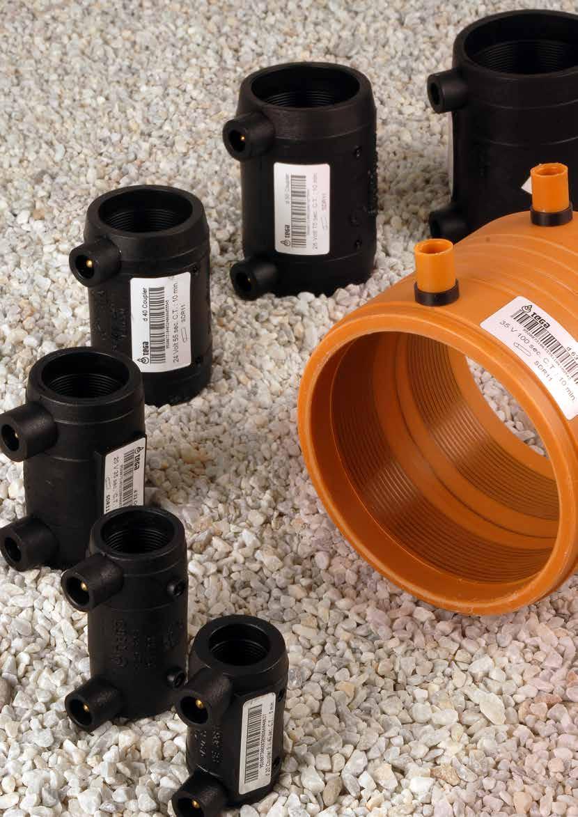
2 hakkımızda/about us TEGA, 25 yılı aşkın süredir plastik borulama ve vana sistemlerinin geliştirilmesinde ve üretiminde lider konumdadır. Geniş PE ve PP ürün gamımız Dünya da 85 ülkede güvenirliğini kanıtlamıştır. İnovasyon işimizin kilit unsurudur. TEGA müşteri ihtiyaçlarını baz alarak yeni fikirler ve çözümler üretmekte, dizayn sınırlarını zorlamaktadır. TEGA projelerinizin gerçekleşmesi için her zaman yanınızda olacaktır. For over 25 years Tega has been a leader in the development and manufacture of fittings and valves for plastic piping systems. Our extensive range of PE and PP fittings are relied upon in 85 countries world wide. Innovation is a key of our business, and Tega continues to push design boundaries by introducing new ideas and solutions based on real customer needs. Let the power of Tega help your project dreams become reality. 1


3 2 hakkımızda/about us

4 hakkımızda/about us TEGA WORLD TEGA ÜRÜNLERİ 85 ÜLKEDE GÜVENLE KULLANILMAKTADIR. TEGA PRODUCTS ARE BEING USED IN 85 COUNTRIES OF THE WORLD SUCCESSFULLY 3


5 Kalite/Quality TEGA nın Kalite politikası; Müşteri gereksinimlerini karşılayacak maksimum kalitede ürün ve servis sağlamaktır. TEGA Müşterilerinin ihtiyaçlarını belirlemekte ve kaynaklarını bu ihtiyaçların hayata geçirilmesi yönünde kullanmaktadır. TEGA ISO 9001:2000 Kalite Yönetim Sistemi ISO 14001:2004 Çevre Yönetim Sistemi OHSAS İş Sağlığı ve Güvenliği Yönetim Sistemi Standartlarını özenle ve % 100 sorumlulukla takip etmektedir. The quality policy of TEGA is to offer the high quality products and services to meet our customers requirements. We adapt our focus and resources to servicing the ever changing needs of customers across many industries. TEGA continually strives to exceed our customer expectations for excellence, value and quality. TEGA manages its business according to international standards associations, including: ISO 9001:2000 Quality Management System Certificate ISO 14001:2004 Environment Management System Certificate OHSAS Safety and Health Management System Certificate 4


6 Projeler/Projects BAE - D 900 mm Manşon UAE - D 900 mm Coupler Türkiye - Soğutma Sistemi Turkey - Cooling System Rusya - Termik Santral Russia - Heat Power Plant Hong Kong - Su Dağıtım Hattı Hong Kong - Water Distribution Lines USA Sleeve - Manşon Uygulaması USA Sleeve - Coupler Installation Yeni Zelanda - D 1000 mm Manşon New Zealand - D1000 mm Coupler 5


7 Projeler/Projects Azerbeycan - Bakü Temiz Su Hattı Su Arıtma Tesisinde 3700 adet EF Semer ve 19,500 Manşon Kullanımı Azerbaijan - Bakü Infiltration - Water Treatment Plant 3,700 EF Saddles and 19,500 Fittings Connection Dubai - D 900 EF Fittingler Dubai - D900 EF Fittings Türkiye - Endüstriyel EF Semer Kullanımı Turkey - Industrial EF Saddle Application Kanada Halifax - D1600 EF Manşon Dünya daki En Büyük Manşon! Canada Halifax - D1600 EF Coupler Application. The Biggest EF Coupler on The World! Kanada - 28 x18 IPS EF Semer Canlı Hat Bağlantısı Canada - 28 x18 IPS EF Saddle Hot Tapping Application 6


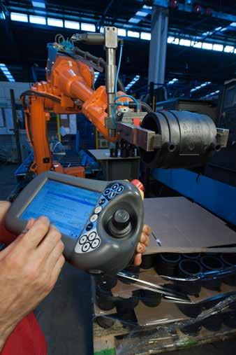
8 EF Kaynakçı Kursları Training TEGA geliştirdiği teknolojinin ancak iyi eğitimli teknik elemanlar vasıtasıyla verimli olarak kullanılabileceğinin bilincindedir. TEGA, teorik ve uygulamalı eğitimler düzenleyerek uygulayıcıları bilgilendirmekte ve sertifika vermektedir. TEGA offers a thorough and intensive training package consisting of both the theoretical and the practical work of jointing PE pipe by Electrofusion technique. 7


![EF Valve Tapping Tee (VS) [1] Certification requested for equivalent metric](/docs-images/84/91102147/images/9-4.jpg "sizes.")
![[2] Sizes and configurations include: Electrofusion Small Branch Saddles - 1](/docs-images/84/91102147/images/9-6.jpg "1/4\" (Base) x 1/2\" (Outlet) - 18\" (Base) x 2\" (Outlet).")
.")

![23 Trade Designation [1] Size Fittings EF Coupler 1/2" - 63" CLD 23 PE EF DOST](/docs-images/84/91102147/images/9-9.jpg "Coupler 4\" - 63\" CLD 23 PE EF Elbow (45) 3/4\" - 6\" CLD 23 PE EF Elbow (90) 3/4\"")

9 Sertifikalar/Certificates NSF International OFFICIAL LISTING NSF International Certifies that the products appearing on this Listing conform to the requirements of NSF/ANSI Standard 61 - Drinking Water System Components - Health Effects This is the Official Listing recorded on February 8, Tega Engineering Industry & Trade Inc. 1. Organize Sanayi Bolgesi Ural Cad. No: 6 Sincan Ankara Turkey Facility: Ankara, Turkey Mechanical Devices Water Water Contact Contact Trade Designation Size Temp Material [1] [2] Service Saddles EF Branch [1] Tapping Sleeves EF Tapping Tee EF Valve Tapping Tee (VS) [1] Certification requested for equivalent metric sizes. [2] Sizes and configurations include: Electrofusion Small Branch Saddles - 1 1/4" (Base) x 1/2" (Outlet) - 18" (Base) x 2" (Outlet). Electrofusion Large Branch Saddles - 3" (Base) x 3" (Outlet) - 63" (Base) x 20" (Outlet). Pipes and Related Products Water Water Contact Contact Temp Material 1/4"-10" x 1/2"-2" - 2" 1/4"x1/2"-63"x20" CLD 23 MLTPL MLTPL Saddle 1 2" - 10" x 1/2" CLD 23 Trade Designation [1] Size Fittings EF Coupler 1/2" - 63" CLD 23 PE EF DOST Coupler 4" - 63" CLD 23 PE EF Elbow (45) 3/4" - 6" CLD 23 PE EF Elbow (90) 3/4" - 6" CLD 23 PE EF Equal Tee 3/4" - 8" CLD 23 PE EF Reducer 1" x 1/2" - 4" x 3" CLD 23 PE [1] Certification requested for equivalent metric sizes. Note: Additions shall not be made to this document without prior evaluation and acceptance by NSF International. 1 of 1 C N. Dixboro Road, Ann Arbor, Michigan USA NSF-MARK /


10 Sertifikalar/Certificates Sadece NFS markası taşıyan ürünler sertifikalıdır. Only the products bearing NFS mark are certified. 9
11 Tega Üretim Standartları Related Standart by TEGA Products - EN Plastics Piping Systems for Water Supply Polyethylene (PE) Part 3 : Fittings - EN Plastics Piping Systems for Water Supply Polyethylene (PE) Part 4 : Valves - EN Plastics Piping Systems for the Supply of Gaseous Fuels Polyethylene (PE) Part 3 : Fittings - EN Plastics Piping Systems for the Supply of Gaseous Fuels Polyethylene (PE) Part 4 : Valves - DVGW GW 335-B2 Plastics Piping for Gas and Water Distribution; Requirements and Testing - DIN Pipe Joints and Elements for High Density Polyethylene (HDPE) Pressure Pipelines (Pipe Bends of Segmental Constructions for Butt-Welding Dimensions) - DIN Pipe Joint Assemblies and Fittings for Types 1 and 2 High Density Polyethylene (HDPE) Pressure Pipes; (Tee and Branches Produced by Segment Inserts for Butt-Welding Dimensions) - DIN Pipe Joints and Elements for High Density Polyethylene (HDPE) Pressure Pipelines (Pipe Bends for Butt-Welding Dimensions) - DIN Pipe Joint Assemblies and Fittings for High Density Polyethylene (HDPE) Pressure Pipelines (Adaptors for fusion jointing, flanges and sealing elements Dimensions) - DIN Pipe Joints and Elements for High Density Polyethylene (HDPE) Pressure Pipelines (General Quality Requirements, Testing - ASTM F-1055 Electrofusion Type Polyethylene Fittings for Outside Diameter Controlled Polyethylene Ürün/Sistem Belgeleri / Product and System Aprovials DVGW Certificate (Size groups 1, 2 and 3 / Electrofusion Fittings / Water and Gas) DVGW Certificate (Size groups 1, 2 and 3 / Spigot Fittings / Water and Gas) DVGW Certificate (Size group 2 / Gate Valves / Water) SVGW Certificate (50 mm -500 mm / Spigot and Electrofusion Fittings) IIP Certificate of Conformity EN (Size group 1 and 2 / Spigot and Electrofusion Fittings) IIP Certificate of Conformity EN (Size group 1 and 2 / Spigot and Electrofusion Fittings) Insta-Cert Certificate EN 12201/Insta SBC (Size group 1 and 2 / Spigot and Electrofusion Fittings) Insta-Cert Certificate EN 1555/Insta SBC 1555 (Size group 1 and 2 / Spigot and Electrofusion Fittings) Watermark Certificate of Conformity Level 1 - AS/NZS 4129 (Electrofusion and Spigot Fittings) FM Approvals Certificate of Compliance Class 1613 NSF Approval NSF/ANSI 61 (Drinking Water System Components) WRAS Material Approval BulgarKontrola Certificate of Conformity ( EN / Spigot and Electrofusion Fittings) TSE (Turkish Standards Institutre) Certificate (TS EN / Spigot and Electrofusion Fittings) TSE (Turkish Standards Institutre) Certificate (TS EN / Ball Valves) TSE (Turkish Standards Institutre) Certificate (TS EN / Spigot and Electrofusion Fittings) TSE (Turkish Standards Institutre) Certificate (TS EN / Gate Valves) ISO 9001 Management System Certificate ISO Environmental Management System Certificate OHSAS Occupational Health and Safety Management System Certificate ABS Certificate of Design Assessment 10
12 Genel İndeks/General Index
13 12

14 EF COUPLER / EF MANŞON SDR 26 PE100 WATER / SU : 6 BAR EF COUPLER / EF MANŞON SDR 17 PE100 GAS / GAZ: 6 BAR WATER / SU: 10 BAR EF COUPLER / EF MANŞON SDR11 PE100 GAS / GAZ : 10 BAR WATER / SU : 16 BAR EF COUPLER / EF MANŞON SDR 9 PE100 WATER / SU : 20 BAR EF COUPLER / EF MANŞON SDR 7,4 PE100 WATER / SU : 25 BAR EF COUPLER / EF MANŞON SDR 6 PE100 WATER / SU : 32 BAR EF DOST COUPLER EF DOST MANŞON SDR 11 PE100 GAS / GAZ: 10 BAR WATER / SU: 16 BAR EF COUPLER (LONG) EF MANŞON (UZUN) SDR11 PE100 GAS / GAZ : 10 BAR WATER / SU : 16 BAR EF TAPPING TEE / EF SERVİS TE SDR 11 PE100 GAS / GAZ: 10 BAR WATER / SU: 16 BAR EF TAPPING TEE WITH BRASS OUTLET / EF SERVİS TE DİŞLİ ÇIKIŞLI SDR11 PE100 WATER / SU : 16 BAR EF VALVE TAPPING TEE (VS TYPE) EF VANALI SERVİS TE (VS TİPİ) SDR 11 PE100 GAS / GAZ : 10 BAR WATER / SU : 16 BAR EF VALVE TAPPING TEE (VA TYPE) EF VANALI SERVİS TE (VA TİPİ) SDR 11 PE100 GAS / GAZ : 10 BAR WATER / SU : 16 BAR EF TAPPING TEE WITH GAS-STOP EF SERVİS TE GAZSTOPLU SDR11 PE100 GAS / GAZ : 1-5 BAR 360 ROTATING OUTLET TAPPING TE 360 DÖNER BAŞLIKLI VANALI SERVİS TE SDR11 PE100 GAS / GAZ : 10 BAR WATER / SU : 16 BAR 360 ROTATING OUTLET TAPPING TE 360 DÖNER BAŞLIKLI SERVİS TE SDR11 PE100 GAS / GAZ : 10 BAR WATER / SU : 16 BAR
15 EF VALVE TAPPING TEE WITH INNER CAP İÇ KAPAKLI VANALI SERVİS TE SDR 11 PE100 GAS / GAZ : 10 BAR WATER / SU : 16 BAR EF SADDLE / EF SEMER SDR11 PE100 GAS / GAZ : 8 BAR WATER / SU : 16 BAR EF SADDLE / EF SEMER SDR17 PE100 GAS / GAZ : 4 BAR WATER / SU : 10 BAR EF SADDLE / EF SEMER SDR11 PE100 GAS / GAZ : 10 BAR WATER / SU : 16 BAR EF SADDLE - STOP SYSTEM EF SEMER - STOP SİSTEM SDR11 PE100 GAS / GAZ : 4 BAR WATER / SU : 10 BAR EF BALLOON SADDLE EF BALON SEMER SDR11 PE100 GAS / GAZ : 10 BAR WATER / SU : 16 BAR EF FLEX SADDLE EF FLEKS SEMERİ SDR11 PE100 GAS / GAZ : 6 BAR WATER / SU : 16 BAR BIG SIZE SADDLE EF SEMER BÜYÜK ÇIKIŞLI EF REPAIR SADDLE EF TAMİR SEMERİ SDR11 PE100 GAS / GAZ : 10 BAR WATER / SU : 16 BAR BIG SIZE EF REPAIR SADDLE BÜYÜK ÇAP EF TAMİR SEMERİ SDR11 PE100 GAS / GAZ : 10 BAR WATER / SU : 16 BAR EF EQUAL TE / EF EŞİT TE SDR11 PE100 GAS / GAZ : 10 BAR WATER / SU : 16 BAR EF REDUCED TE / EF INEGAL TE SDR11 PE100 GAS / GAZ : 10 BAR WATER / SU : 16 BAR EF REDUCER / EF REDÜKSİYON SDR11 PE100 GAS / GAZ : 10 BAR WATER / SU : 16 BAR EF REDUCER (SHORT) FOR DUAL CONTAINMENT PIPES EF REDÜKSİYON (KISA) ÇİFT CİDARLI BORULAR İÇİN EF ELBOW 90 / EF DİRSEK 90 SDR 11 PE100 GAS / GAZ : 10 BAR WATER / SU : 16 BAR


16 EF ELBOW 45 / EF DİRSEK 45 SDR 11 PE100 GAS / GAZ : 10 BAR WATER / SU : 16 BAR EF END CAP / EF KEP SDR 11 PE100 GAS / GAZ : 10 BAR WATER / SU : 16 BAR EF END CAP / EF KEP SDR 17 PE100 GAS / GAZ : 4 BAR WATER / SU : 10 BAR EF END CAP / EF KEP SDR 11 PE100 GAS / GAZ : 10 BAR WATER / SU : 16 BAR 79 EF COUPLER FOR PRE-INSULATED PE PIPING SYSTEM İZOLASYONLU PE BORU EF MANŞON 80 EF FLEXIBLE PATCH FOR SLEEVE COUPLERS SLEEVE MANŞONLAR İÇİN EF KEP PP EF COUPLER / PP EF MANŞON SDR26 PP EF SADDLE / PP EF SEMER SDR26 WATER / SU : 6 BAR TWIN INNER COUPLER PE100 İKİZ İÇ MANŞON PE U COUPLER / U MANŞON SDR11 PE100 WATER / SU : 16 BAR EF DUAL CONTAINMENT FLEX ELBOW SDR22,6 PE100 EF ÇİFT CİDARLI FLEKS DİRSEK DUAL CONTAINMENT COUPLER ÇİFT CİDARLI BORU MANŞONU TYPE / TİP: EF EF TANK PENETRATION SADDLE TANK ÇIKIŞ UCU TYPE / TİP : EF TANK OUTLET FOR PE AND PE-X TANKS/ PE VE PE-X TANKLAR İÇİN ÇIKIŞ TYPE / TİP: EF PE-BRASS TRANSITION COUPLER (FEMALE) PE-PİRİNÇ GEÇİŞ MANŞONU (DİŞİ) TYPE / TİP: EF
 (FEMALE) PE-PİRİNÇ GEÇİŞ DİRSEĞİ (90 ) (DİŞİ) TYPE / TİP: EF 89 90 90 91 PE-BRASS TRANSITION ELBOW (45 ) (MALE) PE-PİRİNÇ GEÇİŞ DİRSEĞİ (45 ) ERKEK) TYPE / TİP: EF PE-BRASS TRANSITION")
 EF COUPLER PE100 YÜKSEK BASINÇLI EF MANŞON PE100 BRASS OUTLET EF SADDLE SDR11")
17 PE-BRASS TRANSITION COUPLER (MALE) PE-PİRİNÇ GEÇİŞ MANŞONU (ERKEK) TYPE / TİP: EF 88 PE-BRASS TRANSITION ELBOW (90 ) (MALE) PE-PİRİNÇ GEÇİŞ DİRSEĞİ (90 ) (ERKEK) TYPE / TİP: EF 89 PE-BRASS TRANSITION ELBOW (90 ) (FEMALE) PE-PİRİNÇ GEÇİŞ DİRSEĞİ (90 ) (DİŞİ) TYPE / TİP: EF PE-BRASS TRANSITION ELBOW (45 ) (MALE) PE-PİRİNÇ GEÇİŞ DİRSEĞİ (45 ) ERKEK) TYPE / TİP: EF PE-BRASS TRANSITION ELBOW (45 ) (FEMALE) PE-PİRİNÇ GEÇİŞ DİRSEĞİ (45 ) (DİŞİ) TYPE / TİP: EF EF FLEX RESTRAINT PE EF FLANGE ADAPTOR PE100 EF FLANŞ ADAPTÖRÜ PE100 EF INNER FLANGE ADAPTOR PE100 EF İÇ FLANŞ ADAPTÖRÜ PE100 EF INNER COUPLER WITH FEMALE THREAD PE100 DİŞİ DİŞLİ EF İÇ MANŞON PE HIGH PRESSURE (SANDWICH) EF COUPLER PE100 YÜKSEK BASINÇLI EF MANŞON PE100 BRASS OUTLET EF SADDLE SDR11 PİRİNÇ ÇIKIŞLI EF SEMER SDR11 GAS / GAZ : 10 BAR WATER / SU : 16 BAR WHEEL EF SADDLE TEKERLEKLİ EF SEMER
18 SPIGOT-METRiK EQUAL TEE / EŞİT TE SDR17 PE100 GAS / GAZ: 10 BAR WATER / SU : 16 BAR TYPE / TİP : SPIGOT EQUAL TEE SEGMENTED EŞİT TE KONFEKSİYON SDR17 PE 100 WATER/SU : 10 BAR TYPE/TİP : SPIGOT EQUAL TEE (SHORT ) EŞİT TE (KISA) SDR17 PE 100 GAS/GAZ : 4 BAR WATER/SU : 10 BAR TYPE/TİP : SPIGOT EQUAL TEE / EŞİT TE SDR11 PE 100 GAS/GAZ: 10 BAR WATER/SU: 16 BAR TYPE/TİP: SPIGOT EQUAL TEE SEGMENTED EŞİT TE KONFEKSİYON SDR11 PE 100 WATER/SU: 16 BAR TYPE/TİP: SPIGOT EQUAL TEE (SHORT) EŞİT TE (KISA) SDR11 PE 100 GAS/GAZ : 10 BAR WATER/SU : 16 BAR TYPE/TİP : SPIGOT REDUCED TEE / INEGAL TE SDR17 PE100 GAS/GAZ: 6 BAR WATER/SU: 10 BAR TYPE/TİP: SPIGOT REDUCED TEE (SHORT) INEGAL TE (KISA) SDR17 PE100 GAS/GAZ : 6 BAR WATER/SU : 10 BAR TYPE/TİP : SPIGOT REDUCED TEE (SHORT) INEGAL TE (KISA) SDR11 PE100 GAS/GAZ : 10 BAR WATER/SU : 16 BAR TYPE/TİP : SPIGOT REDUCED TEE / INEGAL TE SDR11 PE100 GAS/GAZ : 10 BAR WATER/SU : 16 BAR TYPE/TİP : SPIGOT CROSS TEE / KROS TE SDR11 PE100 GAS/GAZ : 10 BAR WATER/SU : 16 BAR TYPE/TİP : SPIGOT CROSS TEE / KROS TE SDR17 PE100 GAS/GAZ : 6 BAR WATER/SU : 10 BAR TYPE/TİP : SPIGOT REDUCING CROSS TEE REDÜKSİYON KROS TE SDR11 PE100 GAS/GAZ : 10 BAR WATER/SU : 16 BAR TYPE/TİP : SPIGOT REDUCING CROSS TEE REDÜKSİYON KROS TE SDR17 PE100 GAS/GAZ : 6 BAR WATER/SU : 10 BAR TYPE/TİP : SPIGOT REDUCER / REDÜKSİYON SDR17 PE100 GAS/GAZ : 6 BAR WATER/SU : 10 BAR TYPE/TİP : SPIGOT
19 SPIGOT-METRiK REDUCER (SHORT) REDÜKSİYON (KISA) SDR17 PE100 GAS/GAZ : 6 BAR WATER/SU : 10 BAR TYPE/TİP : SPIGOT REDUCER / REDÜKSİYON SDR11 PE100 GAS/GAZ : 10BAR WATER/SU : 16 BAR TYPE/TİP : SPIGOT REDUCER (SHORT) REDÜKSİYON (KISA) SDR11 PE100 GAS/GAZ : 10BAR WATER/SU : 16 BAR TYPE/TİP : SPIGOT ELBOW (90 ) / DİRSEK (90 ) SDR17 PE100 GAS/GAZ : 6 BAR WATER/SU : 10 BAR TYPE/TİP : SPIGOT ELBOW (90 ) SEGMENTED DİRSEK (90 ) KONFEKSİYON SDR17 PE100 GAS/GAZ : 6 BAR WATER/SU : 10 BAR TYPE/TİP : SPIGOT ELBOW (90 ) / DİRSEK (90 ) SDR11 PE100 GAS/GAZ : 10 BAR WATER/SU : 16 BAR TYPE/TİP : SPIGOT ELBOW (90 ) SEGMENTED DİRSEK (90 ) KONFEKSİYON SDR11 PE100 GAS/GAZ : 10 BAR WATER/SU : 16 BAR TYPE/TİP : SPIGOT ELBOW (90 ) SEGMENTED (SHORT) DİRSEK (90 ) (KISA) KONFEKSİYON SDR17 PE100 GAS/GAZ : 6 BAR WATER/SU : 10 BAR TYPE/TİP : SPIGOT ELBOW (45 ) / DİRSEK (45 ) SDR17 PE100 GAS/GAZ : 6 BAR WATER/SU : 10 BAR TYPE/TİP : SPIGOT ELBOW (45 ) SEGMENTED(SHORT) DİRSEK (45 ) KONFEKSİYON (KISA) SDR17 PE100 GAS/GAZ : 6 BAR WATER/SU : 10 BAR TYPE/TİP : SPIGOT ELBOW (45 ) SEGMENTED DİRSEK (45 ) KONFEKSİYON SDR17 PE100 GAS/GAZ : 6 BAR WATER/SU : 10 BAR TYPE/TİP : SPIGOT ELBOW (45 ) / DİRSEK (45 ) SDR11 PE100 GAS/GAZ : 10 BAR WATER/SU : 16 BAR TYPE/TİP : SPIGOT ELBOW (45 ) SEGMENTED DİRSEK (45 ) KONFEKSİYON SDR11 PE100 GAS/GAZ : 10 BAR WATER/SU : 16 BAR TYPE/TİP : SPIGOT ELBOW (45 ) SEGMENTED DİRSEK (45 ) KONFEKSİYON SDR11 PE100 GAS/GAZ : 10 BAR WATER/SU : 16 BAR TYPE/TİP : SPIGOT END CAP / KEP SDR17 PE100 GAS/GAZ : 6 BAR WATER/SU : 10 BAR TYPE/TİP : SPIGOT
 FLANŞ ADAPTÖR (KISA) SDR17 PE100 GAS/GAZ : 6 BAR WATER/SU : 10 BAR TYPE/TİP : SPIGOT 154 155 156 FLANGE ADAPTOR FLANŞ ADAPTÖR SDR11 PE100 GAS/GAZ : 10 BAR WATER/SU : 16 BAR")
20 SPIGOT-METRiK END CAP / KEP) SDR11 PE100 GAS/GAZ : 10 BAR WATER/SU : 16 BAR TYPE/TİP : SPIGOT FLANGE ADAPTOR FLANŞ ADAPTÖR SDR17 PE100 GAS/GAZ : 6 BAR WATER/SU : 10 BAR TYPE/TİP : SPIGOT FLANGE ADAPTOR (SHORT) FLANŞ ADAPTÖR (KISA) SDR17 PE100 GAS/GAZ : 6 BAR WATER/SU : 10 BAR TYPE/TİP : SPIGOT FLANGE ADAPTOR FLANŞ ADAPTÖR SDR11 PE100 GAS/GAZ : 10 BAR WATER/SU : 16 BAR TYPE/TİP : SPIGOT FLANGE ADAPTOR (SHORT) FLANŞ ADAPTÖR (KISA) SDR11 PE100 GAS/GAZ : 10 BAR WATER/SU : 16 BAR TYPE/TİP : SPIGOT FLANGE / FLANŞ PN FLANGE / FLANŞ PN10 FLANGE / FLANŞ PN6 PP COATED FLANGE PP KAPLI FLANŞ PN10/ FLANGE ADAPTOR + INDUSTRIAL COMPOSITE FLANGE FLANŞ ADAPTÖRÜ + ENDÜSTRİYEL KOMPOZİT FLANŞ PN10/16 PE-STEEL TRANSITION FITTING (WELDED) PE-ÇELİK GEÇİŞ FİTİNGİ (KAYNAKLI) GAS/GAZ : 10 BAR WATER/SU : 16 BAR TYPE/TİP : SPIGOT PE-BRASS TRANSITION FITTING MALE (THREADED) PE-PİRİNÇ GEÇİŞ FİTİNGİ ERKEK (DİŞLİ) WATER/SU : 16 BAR TYPE/TİP : SPIGOT PE-BRASS TRANSITION FITTING FEMALE (THREADED) PE-PİRİNÇ GEÇİŞ FİTİNGİ DİŞİ (DİŞLİ) WATER/SU : 16 BAR TYPE/TİP : SPIGOT PE THREADED TRANSITION FITTING (MALE) PE DİŞLİ GEÇİŞ PARÇASI (ERKEK) WATER/SU : 16 BAR TYPE/TİP : SPIGOT

21 AKIŞ KONTROL- METRİK PE100 GATE VALVE LONG SPIGOT PE100 SÜRGÜLÜ VANA UZUN SPİGOT FLANGED PE100 GATE VALVE SHORT SPIGOT FLANŞLI PE100 SÜRGÜLÜ VANA KISA SPİGOT PE100 GATE VALVE SHORT SPIGOT PE100 SÜRGÜLÜ VANA KISA SPİGOT PE100 GATE VALVE LONG SPIGOT - FLANGED PE100 SÜRGÜLÜ VANA UZUN SPİGOT/FLANŞLI PE100 GATE VALVE - FLANGED PE100 SÜRGÜLÜ VANA FLANŞLI PE100 GATE VALVE WITH EF SADDLE PE100 SÜRGÜLÜ VANA SEMER ÇIKIŞLI PE BALL VALVE (FULL BORE) PE KÜRESEL VANA (TAM GEÇİŞ) SDR11 PE100 GAS/GAZ : 10 BAR WATER/SU : 16 BAR PE BALL VALVE (REDUCED BORE) PE KÜRESEL VANA (REDÜKSİYON GEÇİŞ) SDR11 PE100 GAS/GAZ : 10 BAR WATER/SU : 16 BAR PE100 BALL CHECK VALVE PE100 KÜRELİ ÇEKVALF PE100 BALL CHECK VALVE - FLANGED PE100 KÜRELİ ÇEKVALF - FLANŞLI PE100 CHECK VALVE WHITH SPRING PE100 YAYLI ÇEKVALF PE100 CHECK VALVE WITH SPRING-FLANGED PE100 YAYLI ÇEKVALF-FLANŞLI PE100 A TYPE IRRIGATION HYDRANT PE100 A TİPİ SULAMA HİDRANTI PE100 D TYPE IRRIGATION HYDRANT PE100 D TİPİ SULAMA HİDRANTI PE100 H TYPE IRRIGATION HYDRANT PE100 H TİPİ SULAMA HİDRANTI


 PE100 UZAKTAN KONTROLLÜ")
22 AKIŞ KONTROL- METRİK PE100 FIRE HYDRANT PE100 YANGIN HİDRATI 178 PE100 SINGLE BALL AIR RELEASE VALVE PE100 TEK KÜRELİ VANTUZ 179 PE100 SINGLE BALL AIR RELEASE VALVE- FLANGED PE100 TEK KÜRELİ VANTUZ FLANŞLI PE100 NON SLAM DYNAMIC AIR RELEASE VALVE PE100 DİNAMİK VANTUZ DARBESİZ PE100 NON SLAM DYNAMIC AIR RELEASE VALVE-FLANGED PE100 DİNAMİK VANTUZ DARBESİZ-FLANŞLI PE100 DOUBLE BALL AIR RELEASE VALVE PE100 ÇİFT KÜRELİ VANTUZ PE100 DOUBLE BALL AIR RELEASE VALVE-FLANGED PE100 ÇİFT KÜRELİ VANTUZ- FLANŞLI PE100 KNIFE VALVE/ PE100 BIÇAK VANA PE100 PURGE VALVE PE100 PURGE VANA EF ACTUATOR BASE EF AKTÜATÖR ALTLIĞI PE100 IRRIGATION HYDRANT (REMOTE CONTROLLED ON-OFF SYSTEM) PE100 UZAKTAN KONTROLLÜ SULAMA HİDRANTI

 DUAL RATED WATER/NATURAL GAS SDR11 ELECTROFUSION TAPPING TEES 205 210 213 SDR11 ELECTROFUSION SMALL BRANCH SADDLES SDR11")
23 SDR26 ELECTROFUSION COUPLER, IPS DUAL RATED WATER NATURAL GAS SDR17 ELECTROFUSION COUPLER, IPS DUAL RATED WATER NATURAL GAS SDR11 ELECTROFUSION COUPLER, IPS DUAL RATED WATER NATURAL GAS SDR6 ELECTROFUSION COUPLER, IPS SDR9 ELECTROFUSION COUPLER, IPS SDR7.4 ELECTROFUSION COUPLER, IPS SDR26 ELECTROFUSION COUPLER, DIPS SDR17 ELECTROFUSION COUPLER, DIPS SDR11 ELECTROFUSION COUPLER, DIPS EF DOST COUPLER SDR 11 ELECTROFUSION LONG COUPLER (IPS) DUAL RATED WATER/NATURAL GAS SDR11 ELECTROFUSION TAPPING TEES SDR11 ELECTROFUSION SMALL BRANCH SADDLES SDR11 ELECTROFUSION VALVE TAPPING TEES SDR11 ELECTROFUSION VALVE TAPPING TEES (VA TYPE)


24 SDR ROTATING TAPPING TEES SDR ROTATING TAPPING TEES SDR11 ELECTROFUSION TAPPING TEES WITH INNER CAP SDR11 ELECTROFUSION FLEX SADDLES SDR11 ELECTROFUSION LARGE BRANCH SADDLES SDR17 ELECTROFUSION LARGE BRANCH SADDLES SDR11 ELECTROFUSION EQUAL TEES SDR11 ELECTROFUSION REDUCERS SDR11 ELECTROFUSION 45 DEGREE ELBOWS EF FLEX RESTRAINT PE SDR11 ELECTROFUSION 90 DEGREE ELBOWS BRASS THREADED OUTLET EF SADDLE SDR11
25 AKIŞ KONTROL- IPS PE100 BALL CHECK VALVE PE100 KÜRELİ ÇEKVALF PE100 BALL CHECK VALVE/FLANGED PE100 KÜRELİ ÇEKVALF - FLANŞLI PE100 CHECK VALVE WITH SPRING PE100 YAYLI ÇEKVALF PE100 CHECK VALVE WHITH SPRING-FLANGED PE100 YAYLI ÇEKVALF-FLANŞLI PE100 A TYPE IRRIGATION HYDRANT PE100 A TİPİ SULAMA HİDRANTI PE100 D TYPE IRRIGATION HYDRANT PE100 D TİPİ SULAMA HİDRANTI PE100 H TYPE IRRIGATION HYDRANT PE100 H TİPİ SULAMA HİDRANTI PE100 FIRE HYDRANT PE100 YANGIN HİDRATI PE100 IRRIGATION HYDRANT (REMOTE CONTROLLED ON-OFF SYSTEM)/ PE100 UZAKTAN KONTROLLÜ SULAMA HİDRANTI PE100 SINGLE BALL AIR RELEASE VALVE PE100 TEK KÜRELİ VANTUZ PE100 SINGLE BALL AIR RELEASE VALVE- FLANGED PE100 TEK KÜRELİ VANTUZ FLANŞLI PE100 NON SLAM DYNAMIC AIR RELEASE VALVE PE100 DİNAMİK VANTUZ DARBESİZ PE100 NON SLAM DYNAMIC AIR RELEASE VALVE-FLANGED PE100 DİNAMİK VANTUZ DARBESİZ-FLANŞLI PE100 DOUBLE BALL AIR RELEASE VALVE PE100 ÇİFT KÜRELİ VANTUZ PE100 DOUBLE BALL AIR RELEASE VALVE-FLANGED PE100 ÇİFT KÜRELİ VANTUZ- FLANŞLI
 PE KÜRESEL VANA (TAM GEÇİŞ)")
26 AKIŞ KONTROL- IPS PE100 PURGE VALVE PE100 PURGE VANA PE100 GATE VALVE LONG SPIGOT PE100 SÜRGÜLÜ VANA UZUN SPİGOT PE100 GATE VALVE LONG SPIGOT - FLANGED PE100 SÜRGÜLÜ VANA UZUN SPİGOT/FLANŞLI PE100 GATE VALVE - FLANGED PE100 SÜRGÜLÜ VANA FLANŞLI PE100 GATE VALVE WITH EF SADDLE PE100 SÜRGÜLÜ VANA SEMER ÇIKIŞLI PE BALL VALVE (FULL BORE) PE KÜRESEL VANA (TAM GEÇİŞ) SDR11 PE100 GAS/GAZ : 10 BAR WATER/SU : 16 BAR 255 PE BALL VALVE (REDUCED BORE) PE KÜRESEL VANA (REDÜKSİYON GEÇİŞ) SDR11 PE100 GAS/GAZ : 10 BAR WATER/SU : 16 BAR


27 MAKİNE- APARATLAR SS REPAIR SADDLE PASLANMAZ ÇELİK TAMİR SEMERİ DUCT FOOT BEND YANGIN HİDRANT ÖKÇESİ SPECIAL DUCT FOOT BEND PE ÖZEL YANGIN HİDRANT ÖKÇESİ EF WELDING MACHINE EF KAYNAK MAKİNESİ BUTT WELDING MACHINE ALIN KAYNAK MAKİNESİ V TYPE ALIGNMENT CLAMP V TİPİ EKSENLEME KELEPÇESİ RE-ROUNDING TOOL OVALLİK KELEPÇESİ COUPLER CLAMP MANŞON KELEPÇESİ HAND SCRAPING TOOLS BORU KAZIMA APARATLARI SQUEEZING TOOL FOR EF SADDLE SEMER SIKTIRMA APARATLARI COUPLER PULLING TOOL MANŞON ÇEKTİRME SETİ


28 MAKİNE- APARATLAR PIPE CUTTER (HAND TYPE) BORU KESME MAKASI TELESCOPIC PIPE CUTTER TELESKOPİK BORU KESİCİ TEGA TELESCOPIC EXTENSIONS WITH SURFACE BOX FOR PE GATE VALVE TEGA PE-SÜRGÜLÜ VANALAR İÇİN BUŞAKLELİ TELESKOPİK UZATMA KOLLARI 267 TELESCOBIC EXTENSION FOR GATE VALVE SÜRGÜLÜ VANA İÇİN TELESKOPİK UZATMA KOLLARI TELESCOBIC EXTENSION FOR BALL VALVE KÜRESEL VANA İÇİN TELESKOPİK UZATMA KOLLARI SURFACE BOX BUŞAKLE KAZANI EF SADDLE DRINLLING TOOL PP SEMER DELME APARATI TAKIMI EXTERNAL BUTT FUSION PRES- SURE TEST TOOL HARİCİ ALIN KAYNAK BASINÇ TEST APARATI

29
30 EF ÜRÜNLER EF PRODUCTS
 L (mm) box sizes nos/box type 63 1800001 0,12 75 83 304030 30 A 75 1800002 0,13 87 83 604030 36 A 90 1800003 0,25 103 100 304030 18 A 110 1800004 0,34 125 100 604030 24 A 125 1800006 0,38 140")
31 EF COUPLER / EF MANŞON SDR 26 PE100 WATER / SU : 6 BAR TYPE A TYPE B d CODE Kg. D (mm) L (mm) box sizes nos/box type , A , A , A , A , A , B , B , B , B , B , B , B , B , B , B , B , B , B , B , B , B , B , B , B , B , B Manşonun her iki tarafı ayrı kaynak olmaktadır. (2 ends of coupler fused separately) Karton kutu kullanılmaz.sadece Euro paletler kullanılmaktadır. No box is used. (Only Euro pallets are being used.) 30
32 EF COUPLER / EF MANŞON SDR 17 PE100 GAS / GAZ: 6 BAR WATER / SU: 10 BAR d CODE Kg. D (mm) L (mm) box sizes nos/box , , , , , , , , , , , , , , , , , Manşonun her iki tarafı ayrı kaynak olmaktadır. (2 ends of coupler fused separately) Karton kutu kullanılmaz.sadece Euro paletler kullanılmaktadır. No box is used. (Only Euro pallets are being used.) 31
33 EF COUPLER / EF MANŞON SDR11 PE100 GAS / GAZ : 10 BAR WATER / SU : 16 BAR TYPE A TYPE B d CODE Kg. D (mm) L (mm) box sizes nos/box type , A , A , A , A , A , A , A , A , A , A , A , A , A , A , A , B , B , B , B , B , B , B , B , B , B , B , B , B Manşonun her iki tarafı ayrı kaynak olmaktadır. (2 ends of coupler fused separately) Karton kutu kullanılmaz.sadece Euro paletler kullanılmaktadır. (No box is used. Only Euro pallets are being used.) 32
34 EF COUPLER / EF MANŞON SDR 9 PE100 WATER / SU : 20 BAR TYPE A TYPE B d CODE Kg. D (mm) L (mm) box sizes nos/box type , A , A , A , A , A , B , B , B , B , B , B , B , B , B , B , B , B , B , B Manşonun her iki tarafı ayrı kaynak olmaktadır. (2 ends of coupler fused separately) Karton kutu kullanılmaz.sadece Euro paletler kullanılmaktadır. No box is used. (Only Euro pallets are being used.) 33
35 EF COUPLER / EF MANŞON SDR 7,4 PE100 WATER / SU : 25 BAR TYPE A TYPE B d CODE Kg. D (mm) L (mm) box sizes nos/box type , A , A , A , A , A , B , B , B , B , B , B , B , B , B , B , B , B , B , B Manşonun her iki tarafı ayrı kaynak olmaktadır. (2 ends of coupler fused separately) Karton kutu kullanılmaz.sadece Euro paletler kullanılmaktadır. No box is used. (Only Euro pallets are being used.) 34
36 EF COUPLER / EF MANŞON SDR 6 PE100 WATER / SU : 32 BAR TYPE A TYPE B d CODE Kg. D (mm) L (mm) box sizes nos/box tip , A , A , A , A , A , B , B , B , B , B , B , B , B , B , B , B Manşonun her iki tarafı ayrı kaynak olmaktadır. (2 ends of coupler fused separately) 35


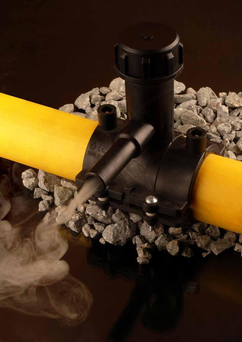
37 TEGA DOST MANŞON Test Point Test Noktası TEGA DOST COUPLER 4 Welding Zone 4 Ayrı Kaynak Bölgesi The Leading Edge of Electrofusion Technology! EF Teknolojisinde Gelinen Son Nokta! Oval Pipe / Oval Boru Bevelled Entrance Konik Giriş Circular Pipe / Dairesel Boru Deflection can cause ovality. The ovality of the pipe can be solved by using conical enterance of the coupler. Dost coupler can tolerate up to 10% ovality of the pipe Oval Boruların Manşona sokulması zor bir işlemdir. Dost Manşon konik girişi yardımıyla boruda ki ovallik alınır. Manşona borular rahatlıkla sürülür ve borudaki % 10 a kadar ovallik giderilir. 9 Dost Coupler can accommodate up to 9 deflection of the pipe without using any tool Borulardaki 9 ye kadar olan eksen sapmaları giderilir. Make the hydraulic test without filling the pipe line with water Boru hattı boşken BASINÇ TEST i yapılmasını sağlayan inovatif tasarım The winner of world innovation award DÜNYA İNOVASYON ÖDÜLÜ


38 EF DOST COUPLER / EF DOST MANŞON SDR 11 PE100 GAS / GAZ: 10 BAR WATER / SU: 16 BAR L d D1 L d D1 TYPE A TYPE B d CODE Weight (kg) D1 L SDR TYPE , B , B , B , B , B , B , B , B , B , A , A , A , A , A , A , A , A , A , A , A , A , A , A A , A GAS / GAZ: 4 BAR - WATER / SU: 10 BAR 37
39 EF COUPLER (LONG) EF MANŞON (UZUN) SDR11 PE100 GAS / GAZ : 10 BAR WATER / SU : 16 BAR D L d d CODE Kg. D (mm) L (mm) box sizes nos/box , , , , , , , , ,
 L (mm) box sizes nos/box type 4020 1803117 0,29 105 44 403030 25 A 4025 1803118 0,30 105 44 403030 25 A 4032 1803119 0,31 105 47 403030 25 A 5020 1803125 0,33 105 52 403030 15 A 5025 1803126")

40 EF TAPPING TEE / EF SERVİS TE SDR 11 PE100 GAS / GAZ: 10 BAR WATER / SU: 16 BAR TYPE A TYPE B TYPE C TYPE D TYPE E Dd CODE Kg. H (mm) L (mm) box sizes nos/box type , A , A , A , A , A , A , A , A , A , A , B , B , A , A , A , A , B , B , A , A , A , A , A , A , A , A 39
41 EF TAPPING TEE / EF SERVİS TE SDR 11 PE100 GAS / GAZ : 10 BAR WATER / SU : 16 BAR Dd CODE Kg. H (mm) L (mm) box sizes nos/box type , A , A , A , A , A , A , A , A , A , A , C , C , C , C , C , C , D , D , D , D , D , D , D , D , D , D , D , D , D , D , D , D , D , D , D , D , D , D , D , D , D , D , D , D , D , D , D , D 40
42 EF TAPPING TEE / EF SERVİS TE SDR 11 PE100 GAS / GAZ : 10 BAR WATER / SU : 16 BAR Dd CODE Kg. H (mm) L (mm) box sizes nos/box type , D , D , D , D , D , D , D , D , D , D , E , E , E , E , E , E Sadece SDR17 borularda delme işlemi yapılabilir. (Only SDR17 pipe for drilling) 41
43 EF TAPPING TEE WITH BRASS OUTLET EF SERVİS TE DİŞLİ ÇIKIŞLI SDR11 PE100 WATER / SU : 16 BAR Dd CODE Kg. H (mm) L (mm) box sizes nos/box 9020/25/ , /25/ , /25/ , /25/ , /25/ , /25/ , /25/ , /25/ , /25/ , /25/ , /25/ , /25/ , Sadece SDR17 borularda delme işlemi yapılabilir. (Only SDR17 pipe for drilling) 42
 L (mm) box sizes nos/box type 6320 1803160 0,85 160 50 403030 10 A 6325 1803161 0,85 160 50 403030 10 A 6332 1803162 0,87 160 75 304030 10 A 6340 1803163 0,88 160 75 403030 10 A 6350 1803164")


44 EF VALVE TAPPING TEE (VS TYPE) EF VANALI SERVİS TE (VS TİPİ) SDR 11 PE100 GAS / GAZ : 10 BAR WATER / SU : 16 BAR TYPE A TYPE B TYPE C TYPE E Dd CODE Kg. H (mm) L (mm) box sizes nos/box type , A , A , A , A , B , B , A , A , A , A , B , B , A , A , A , A , C , C , A , A , A , A , C , C , A , A , A , A 43
45 EF VALVE TAPPING TEE (VS TYPE) / EF VANALI SERVİS TE (VS TİPİ) SDR 11 PE100 GAS / GAZ : 10 BAR WATER / SU : 16 BAR Dd CODE Kg. H (mm) L (mm) box sizes nos/box type , C , C , C , C , C , C , C , C , C , C , C , C , C , C , C , C , C , C , C , C , C , C , C , C , C , C , C , C , C , C , C , C , E , E , E , E , E , E , E , E , E , E , E , E , E , E , E , E , E , E 44
 L (mm) box sizes nos/box type 5020 1803417 1,12 105 52 403030 15 A 5025 1803418 1,14 105 54 403030 15 A 5032 1803419 1,15 105 85 403030 15 A 6320 1803420 1,12 105 52 403030 12 A 6325 1803339")
46 EF VALVE TAPPING TEE (VA TYPE) EF VANALI SERVİS TE (VA TİPİ) SDR 11 PE100 GAS / GAZ : 10 BAR WATER / SU : 16 BAR TYPE A TYPE B TYPE C TYPE D TYPE E Dd CODE Kg. H (mm) L (mm) box sizes nos/box type , A , A , A , A , A , A , A , B , B , A , A , A , A , B , B , A , A , A , A , A , A , A , A , A , A , A 45
47 EF VALVE TAPPING TEE (VA TYPE) EF VANALI SERVİS TE (VA TİPİ) SDR 11 PE100 GAS / GAZ : 10 BAR WATER / SU : 16 BAR Dd CODE Kg. H (mm) L (mm) box sizes nos/box type , A , A , A , A , A , A , A , C , C , C , C , C , C , D , D , D , D , D , D , D , D , D , D , D , D , D , D , D , D , D , D , D , D , D , D , D , D , D , D , D , D , D , D , D , D , D , D , D , D , D 46
48 EF VALVE TAPPING TEE (VA TYPE) EF VANALI SERVİS TE (VA TİPİ) SDR 11 PE100 GAS / GAZ : 10 BAR WATER / SU : 16 BAR Dd CODE Kg. H (mm) L (mm) box sizes nos/box type , D , D , D , D , D , E , E , E , E , E , E Sadece SDR17 borularda delme işlemi yapılabilir. (Only SDR17 pipe for drilling) 47

49 OPERASYON BASINÇ ARALIĞI OPERATING PRESSURE RANGE 1-5 BAR Ø20 Ø32 Vn m3/h(sc) AT 1-5 BAR Vn m3/h(sc) AT 1-5 BAR EF TAPPING TEE WITH GAS-STOP EF SERVİS TE GAZSTOPLU SDR11 PE100 GAS / GAZ : 1-5 BAR Dd CODE Kg. H (mm) L (mm) box sizes nos/box , , , , , , , , , , , , , , , , , , , , , , , , , , , , , , , , Sadece SDR17 borularda delme işlemi yapılabilir. (Only SDR17 pipe for drilling) 48
50 360 ROTATING OUTLET TAPPING TE 360 DÖNER BAŞLIKLI VANALI SERVİS TE SDR11 PE100 GAS / GAZ : 10 BAR WATER / SU : 16 BAR H L d D/2 Dd CODE Kg. L(mm) box sizes nos/box , , , , , , , , , , , , , , , , , , , , , , , , , , , , ,
51 360 ROTATING OUTLET TAPPING TE 360 DÖNER BAŞLIKLI SERVİS TE SDR11 PE100 GAS / GAZ : 8 BAR WATER / SU : 16 BAR Dd CODE Kg. L(mm) box sizes nos/box , , , , , , , , , , , , , , , , , , ,
52 360 ROTATING OUTLET TAPPING TE 360 DÖNER BAŞLIKLI SERVİS TE SDR11 PE100 GAS / GAZ : 10 BAR WATER / SU : 16 BAR H L d Dd CODE Kg. L(mm) box sizes nos/box , , , , , , , , , , , , , , , , , , , , , , , , , , , , , D/2 51
53 360 DÖNER BAŞLIKLI SERVİS TE 360 ROTATING OUTLET TAPPING TE SDR11 PE100 GAS / GAZ : 8 BAR WATER / SU : 16 BAR Dd CODE Kg. L(mm) box sizes nos/box , , , , , , , , , , , , , , , , , , ,
54 EF VALVE TAPPING TEE WITH INNER CAP İÇ KAPAKLI VANALI SER TE SDR11 PE100 GAS / GAZ : 10 BAR WATER / SU : 16 BAR H L D/2 d Dd CODE Kg. L(mm) box sizes nos/box , , , , , , , , , , , , , , , , , , , , , , , , ,
55 EF VALVE TAPPING TEE WITH INNER CAP İÇ KAPAKLI VANALI SER TE SDR11 PE100 GAS / GAZ : 10 BAR WATER / SU : 16 BAR Dd CODE Kg. L(mm) box sizes nos/box , , , , , , , , , , , , , ,
56 EF SADDLE / EF SEMER SDR11 PE100 GAS / GAZ : 8 BAR WATER / SU : 16 BAR Dd CODE Kg. L(mm) box sizes nos/box , , , , , , , , , , , , , , , , , , , , , , , , , , , , , , , , , , , , , ,
57 EF SADDLE / EF SEMER SDR11 PE100 GAS / GAZ : 8 BAR WATER / SU : 16 BAR 56 Dd CODE Kg. L(mm) box sizes nos/box , , , , , , , , , , , , , , , , , , , , , , , , , , , , , , , , , , , , , , , , , , , , , , , , , , , , ,
58 EF SADDLE / EF SEMER SDR11 PE100 GAS / GAZ : 8 BAR WATER / SU : 16 BAR Dd CODE Kg. L(mm) box sizes nos/box , , , , , , , , , , , , , , , , , , , , , , , , , , , , , , , , , , , , , , , , , , , , , , , , , , , , ,
59 EF SADDLE / EF SEMER SDR11 PE100 GAS / GAZ : 8 BAR WATER / SU : 16 BAR 58 Dd CODE Kg. L(mm) box sizes nos/box , , , , , , , , , , , , , , , , , , , , , , , , , , , , , , , , , , , , , , , , , , , , , , , , , , , , , ,
60 EF SADDLE / EF SEMER SDR17 PE100 GAS / GAZ : 4 BAR WATER / SU : 10 BAR Dd CODE Kg. L(mm) box sizes nos/box , , , , , , , , , , , , , , , , , , , , , , , , , , , , , , , ,
61 EF SADDLE / EF SEMER SDR17 PE100 GAS / GAZ : 4 BAR WATER / SU : 10 BAR Dd CODE Kg. L(mm) box sizes nos/box , , , , , , , , , , , , , , , , , , , , , , , , , , , , , , ,
 box sizes nos/box type 4020 1809010 0,18 75 403030 35 A 4025 1809011 0,19 75 403030 35 A 4032 1809012 0,20 75 403030 35 A 5020 1809013 0,34 77 403030 24 A 5025 1809014 0,35 77 304030 24 A 5032")
62 EF SADDLE / EF SEMER SDR11 PE100 GAS / GAZ : 10 BAR WATER / SU : 16 BAR TYPE A TYPE B TYPE C Dd CODE Kg. H (mm) box sizes nos/box type , A , A , A , A , A , A , A , A , A , A , A , A , A , A , A , A , A , A , A , A , A , A , A , B , B 61
63 EF SADDLE / EF SEMER SDR11 PE100 GAS / GAZ : 10 BAR WATER / SU : 16 BAR Dd CODE Kg. H (mm) box sizes nos/box type , A , A , A , A , B , B , A , A , A , A , B , B , B , B , B , B , B , B , B , B , B , B , B , B , B , B , B , B , B , B , B , B , B , B , B , B , B , B , B , B , B , B , C , C , C , C , C , C 62
64 EF SADDLE / EF SEMER SDR11 PE100 GAS / GAZ : 10 BAR WATER / SU : 16 BAR Dd CODE Kg. H (mm) box sizes nos/box type , C , C , C , C , C , C , C , C , C , C , C , C , C , C , C , C , C , C , C , C , C , C , C , C , C , C , C , C , C , C 63
 d (mm) TYPE 63 1825007 1,44 92 74,9 A 90 1809000 2,73 120 100 A 110 1809001 3,72 140 112,8 A 125 1809002 4,45 157 125,4 A 160 1809003 17,73 205")

65 EF SADDLE - STOP SYSTEM EF SEMER - STOP SİSTEM SDR11 PE100 GAS / GAZ : 4 BAR WATER / SU : 10 BAR TYPE A TYPE B D (mm) CODE Kg. L (mm) d (mm) TYPE , ,9 A , A , ,8 A , ,4 A , ,8 B , ,8 B , ,9 B , ,8 B , B , ,5 B , B Bu ürün sadece Ravetti için üretilmekte olup satışı Ravetti firması tarafından yapılmaktadır. This product is produced for Ravetti SA and sell by only Ravetti. 64
 2 1/2 75 2204342 2,25 138 2 1/2 90 2204343 2,24 138 2 1/2 110 2204344 2,22 137 2 1/2 125 2204345 2,22 137 2 1/2")

66 EF BALLOON SADDLE EF BALON SEMER SDR11 PE100 GAS / GAZ : 10 BAR WATER / SU : 16 BAR D d CODE Kg. L(mm) 2 1/ , / , / , / , / , / , / , / , / , / , / , / , / , / ,
67 EF FLEX SADDLE / EF FLEKS SEMER SDR11 PE100 GAS / GAZ : 6 BAR WATER / SU : 16 BAR d L D (mm) CODE Kg. L (mm) d (mm) nos/box , x40x , x40x , x40x , x40x , x40x , x40x , x40x , x40x , x40x , x40x , x40x , x40x , x40x , x40x , x40x , x40x , x40x , x40x , x40x , x40x , x40x , x40x , x40x , x40x , x40x , x40x , x40x , x40x , x40x
68 EF FLEX SADDLE / EF FLEKS SEMER SDR11 PE100 GAS / GAZ : 6 BAR WATER / SU : 16 BAR D (mm) CODE Kg. L (mm) d (mm) nos/box , x40x , x40x , x40x , x40x , x40x , x40x , x40x , x40x


69 BIG SIZE SADDLE EF SEMER BÜYÜK ÇIKIŞLI PE100 (D) (d) MAIN OUTLET d D L 68

70 EF REPAIR SADDLE EF TAMİR SEMERİ SDR11 PE100 GAS / GAZ : 10 BAR WATER / SU : 16 BAR TYPE A TYPE B TYPE C D CODE Kg. d box sizes nos/box Type , A , A , A , A , A , B , B , B , B , B , C , C , C , C , C , C , C , C , C , C , C , C 69
 L box sizes nos/box 110 1810039 0,60 80 150 604030 24 125 1810041 0,60 80 180 604030 18 140 1811697 0,60 120 200 604030 12 160 1811698 0,60 120 200 604030 12 180 1811699 0,60 150 255 604030")
71 BIG SIZE EF REPAIR SADDLE BÜYÜK ÇAP EF TAMİR SEMERİ SDR11 PE100 GAS / GAZ : 10 BAR WATER / SU : 16 BAR L d D d (max. Closing hole D CODE Kg. diameter) L box sizes nos/box , , , , , , , , , , , , , , , , , , , , , , ,
 L1(mm) box sizes nos/box Type 25 1816011 0,07 108 37 403015 50 A 32 1816013 0,15 128 41 403015 25 A 40 1816016 0,22 147 49 403030 35 A 50 1816018 0,31 162 49 604030 40 A 63 1816021 0,57 186 61")
72 EF EQUAL TE / EF EŞİT TE SDR11 PE100 GAS / GAZ : 10 BAR WATER / SU : 16 BAR TYPE A TYPE B TYPE C d CODE Kg. L(mm) L1(mm) box sizes nos/box Type , A , A , A , A , A , A , A , A , A , B , B , B , C , C , C , C Karton kutu kullanılmaz.sadece Euro paletler kullanılmaktadır. No box is used. (Only Euro pallets are being used.) 71
 L1 (mm) box sizes nos/box Type 3220 1817027 0,11 128 41 304015 25 A 3225 1817028 0,11 128 41 304015 25 A 5032 1817033 0,27 162 49 604030 25 A 6332 1817037 0,50 186 61 604030 25 A 6340 1817038")

73 EF REDUCED TE / EF INEGAL TE SDR11 PE100 GAS / GAZ : 10 BAR WATER / SU : 16 BAR d2 TYPE A TYPE B d1 d1d2 CODE Kg. L (mm) L1 (mm) box sizes nos/box Type , A , A , A , A , A , A , A , A , A , A , A , A , A , A , A , A , B , B , B , B , B , B , B , B , B , B , B , B , B , B 72
 box sizes nos/box Type 2520 1818016 0,04 72 403015 100 A 3220 1818017 0,04 90 403015 60 A 3225 1818018 0,05 90 403015 60 A 4032 1818024 0,09 117 403030 70 A 5032 1818029 0,15 131 403030 45 A")
74 EF REDUCER / EF REDÜKSİYON SDR11 PE100 GAS / GAZ : 10 BAR WATER / SU : 16 BAR TYPE A TYPE B d1d2 CODE Kg. L (mm) box sizes nos/box Type , A , A , A , A , A , A , A , A , A , A , A , A , A , A , A , A , A , A , B , B , B , B , B , B , B , B , B , B , B , B , B 73
75 EF REDUCER / EF REDÜKSİYON SDR11 PE100 GAS / GAZ : 10 BAR WATER / SU : 16 BAR d1d2 CODE Kg. L (mm) box sizes nos/box Type , B , B , B , B , B , B , B , B , B , B , B , B , B , B , B , B , B , B , B , B , B , B , B , B , B , B Karton kutu kullanılmaz.sadece Euro paletler kullanılmaktadır. No box is used. (Only Euro pallets are being used.) 74

76 EF REDUCER (SHORT) FOR DUAL CONTAINMENT PIPES EF REDÜKSİYON (KISA) ÇİFT CİDARLI BORULAR İÇİN d1d2 CODE Kg. L (mm) box sizes nos/box , ,
 L1 (mm) box sizes nos/box Type 20 1819009 0,08 98 38 304015 60 B 25 1819010 0,05 98 38 304015 50 A 32 1819011 0,09 109 41 304030 60 B 40 1819013 0,18 131 47 304030 35 B 50 1819015 0,27 155 51")
77 EF ELBOW 90 / EF DİRSEK 90 SDR 11 PE100 GAS / GAZ : 10 BAR WATER / SU : 16 BAR TYPE A TYPE B TYPE C TYPE D d CODE Kg. L(mm) L1 (mm) box sizes nos/box Type , B , A , B , B , B , A , B , A , A , A , C , C , C , C D C D Karton kutu kullanılmaz. Sadece Euro paletler kullanılmaktadır. No box is used. (Only Euro pallets are being used.). 76
 L1 (mm) box sizes nos/box Type 25 1819061 0,06 106 38 403015 80 B 32 1819062 0,05 116 41 403030 80 B 40 1819064 0,13 139 47 403030 55 B 50 1819066 0,23 166 51 403030 32 B 63 1819182 0,40 197 58")

78 EF ELBOW 45 / EF DİRSEK 45 SDR 11 PE100 GAS / GAZ : 10 BAR WATER / SU : 16 BAR TYPE A TYPE B TYPE C TYPE D d CODE Kg. L(mm) L1 (mm) box sizes nos/box Type , B , B , B , B , A , B , A , A , A , C , C , C , C , D , C , D Karton kutu kullanılmaz. Sadece Euro paletler kullanılmaktadır. No box is used. (Only Euro pallets are being used.) 77
 L(mm) box sizes nos/box 20 1822025 0,05 33 68 304015 100 25 1822026 0,07 41 82 304015 80 32 1822028 0,09 48 89 304030 60 40 1822029 0,12 55 97 304030 50 50 1822032 0,19 67 110 304030 40 63")
79 EF END CAP / EF KEP SDR 11 PE100 GAS / GAZ : 10 BAR WATER / SU : 16 BAR d CODE Kg. D(mm) L(mm) box sizes nos/box , , , , , , , , , , , , , , , , , , , , , , , , , Karton kutu kullanılmaz.sadece Euro paletler kullanılmaktadır. No box is used. (Only Euro pallets are being used.) 78
 L(mm) box sizes nos/box 200 1822018 4,66 245 220 604045 6 225 1822080 6,24 260 230 604030 2 250 1822019 8,10 285 240 604045 2 280 1822081 11,20 325 240 604045 2 315 1822020 15,05 360 345 604045")
80 L EF END CAP / EF KEP SDR 17 PE100 GAS / GAZ : 6 BAR WATER / SU : 10 BAR D d CODE Kg. D(mm) L(mm) box sizes nos/box , , , , , , , , , , , , Karton kutu kullanılmaz.sadece Euro paletler kullanılmaktadır. No box is used. (Only Euro pallets are being used.) EF END CAP / EF KEP SDR 11 PE100 GAS / GAZ : 10 BAR WATER / SU : 16 BAR Tek parça enjeksiyon baskı One piece injected d CODE Kg. D(mm) L(mm) box sizes nos/box , , , , , , , , Karton kutu kullanılmaz.sadece Euro paletler kullanılmaktadır. No box is used. (Only Euro pallets are being used.) 79


81 EF COUPLER FOR PRE-INSULATED PE PIPING SYSTEM İZOLASYONLU PE BORU EF MANŞON L D d CODE Kg. D (mm) L(mm) , , , , , , , , , , , , , , , , , , d EF FLEXIBLE PATCH FOR SLEEVE COUPLERS SLEEVE MANŞONLAR İÇİN EF KEP Main Pipe size/ Boru çapı CODE d d: diameter of hole (delik çapı) 80
 L (mm) box sizes nos/box 110 1800005 0,33 128 110 604030 24 160 1800009 0,80 175 160 604045 12 200 1800013 1,16 220 165 604045 8 250 1800016 1,68 275 165 604030 4 315 1800019 2,63 345")
 PP EF SADDLE/ PP EF SEMER SDR 26 WATER / SU : 6 BAR D/d CODE Kg.")
82 PP EF COUPLER / PP EF MANŞON SDR 26 WATER / SU : 6 BAR d CODE Kg. D (mm) L (mm) box sizes nos/box , , , , , , , , Karton kutu kullanılmaz.sadece Euro paletler kullanılmaktadır. No box is used. (Only Euro pallets are being used.) PP EF SADDLE/ PP EF SEMER SDR 26 WATER / SU : 6 BAR D/d CODE Kg. L(mm) box sizes nos/box 200/ , x40x / , x40x / , x40x / , x40x / , x40x / , x40x


83 TWIN INNER COUPLER İKİZ İÇ MANŞON PE100 - Talebe bağlı olarak D160 - D1600 aralığında üretilmektedir. - Available on request all the size from D160 to D
 L (mm) box sizes nos/box 32 1800285 90 110 304015 25")
84 U COUPLER / U MANŞON SDR11 PE100 WATER / SU : 16 BAR d CODE D (mm) L (mm) box sizes nos/box


85 EF DUAL CONTAINMENT FLEX ELBOW TEGA-HALOCK SDR 26 PE100 For dual containment pipe CODE d D L kg box sizes nos/box 110/ ,7 185, ,
86 DUAL CONTAINMENT COUPLER ÇİFT CİDARLI BORU MANŞONU TYPE / TİP: EF d Code Description Kg. D(mm) D1(mm) L(mm) box sizes nos/box For 110x90 dual 1, containment pipe 85
87 EF TANK PENETRATION SADDLE TANK ÇIKIŞ UCU TYPE / TİP : EF d1 CODE Kg. D(mm) L (mm) box sizes nos/box , , ,

88 TANK OUTLET FOR PE AND PE-X TANKS PE VE PE-X TANKLAR İÇİN ÇIKIŞ TYPE / TİP: EF D (mm) d (mm) , 40, 50, 63, 75, 90, 110, 125, 140, 160, 180, 200, 225, 280, 315, 355, 400, 450, 500, 560, 630, 710, 800, 900, 1000,
 D (mm) box sizes nos/box 20-1/2 1823000 0,12 108 33 403015 75 25-3/4 1823002 0,17 114 41 403015 50 32-1 1823003 0,26 130 48 403030 60 40-1 1/4 1823006 0,32 140 55 403030 40 50-1 1/2 1823007")
89 PE-BRASS TRANSITION COUPLER (FEMALE) PE-PİRİNÇ GEÇİŞ MANŞONU (DİŞİ) TYPE / TİP: EF d-rp CODE Kg. L(mm) D (mm) box sizes nos/box 20-1/ , / , , / , / , , PE-BRASS TRANSITION COUPLER (MALE) PE-PİRİNÇ GEÇİŞ MANŞONU (ERKEK) TYPE / TİP: EF d-rp CODE Kg. L(mm) D (mm) box sizes nos/box 20-1/ , / , / , / , / , , / , / , / , , / , , , Steel / Çelik 88
 D (mm) box sizes nos/box 20-1/2 1823027 0,18 155 36 403030 60 20-3/4 1823089 0,18 155 36 403030 60 25-3/4 1823028 0,18 155 37 403030 60 32-1 1823029 0,32 180 44 403030 40 32-3/4 1823069 0,32")
90 PE-BRASS TRANSITION ELBOW (90 ) (MALE) PE-PİRİNÇ GEÇİŞ DİRSEĞİ (90 ) (ERKEK) TYPE / TİP: EF d-r CODE Kg. L(mm) D (mm) box sizes nos/box 20-1/ , / , / , , / , / , / , / , , / , , , Steel / Çelik PE-BRASS TRANSITION ELBOW (90 ) (FEMALE) PE-PİRİNÇ GEÇİŞ DİRSEĞİ (90 ) (DİŞİ) TYPE / TİP: EF d-rp CODE Kg. L(mm) D (mm) box sizes nos/box 20-1/ , / , , / , / , ,
91 PE-BRASS TRANSITION ELBOW (45 ) (MALE) PE-PİRİNÇ GEÇİŞ DİRSEĞİ (45 ) ERKEK) TYPE / TİP: EF d-r CODE Kg. L(mm) D (mm) box sizes nos/box 20-1/ , / , / , , / , / , / , / , , / , , , Steel / Çelik PE-BRASS TRANSITION ELBOW (45 ) (FEMALE) PE-PİRİNÇ GEÇİŞ DİRSEĞİ (45 ) (DİŞİ) TYPE / TİP: EF d-rp CODE Kg. L(mm) D (mm) box sizes nos/box 20-1/ , / , , / , / , ,
92 EF FLEX RESTRAINT PE100 Main Pipe size/ Boru çapı (R) CODE L H W Maksimum eksenel yük 42,3 kn. Beton duvar geçişlerinde pratik çözüm. - Max permissible axial fource 42,3kN Simple solution for concrete wall transition. SORUN / PROBLEM - Isıl genleşmeden dolayı, PE boru hareket eder ve boru - beton arasında boşluk oluşur. - Because of the thermal expansion, PE pipe moves each side and a gap occurs between pipe and concrete. EF FLEX RESTRAINT ler boruya kaynatılır. EF FLEX RESTRAINTs are welded to the pipe. ÇÖZÜM / SOLUTION - Borunun hareket etmesini ve boşluk oluşmasını engellemek için, EF FLEX RESTRAINT ler boruya kaynatılarak sabitlenir. - To prevent movement of pipe and gap, EF FLEX RESTRAINTs are fixed to the pipe by welding. - İki tahta blok betondan ayırılır. - Two wood blocks are separated from concrete. - Sadece beton blok kalır ve EF Flex Restraintler borunun stabil kalmasını sağlar. -Only concrete block stands and EF Flex Restraints keep pipe stable. - Beton, iki tahta blok arasına dökülür - Concrete is built between two wood blocks. 91
93 - Beton duvar geçişlerinde kritik kuvvet, borudaki ısıl genleşmenin neden olduğu eksenel yüktür. - Tega Flex parçalarının herbiri 42,3 kn a kadar eksenel (yanal) yük taşıyabilir. - Herbir boru çapı için gerekli flex sayısı tabloda verilmiştir. - For wall transition the only critical force on the pipe is thermal expension of the pipe system - Tega EF Flex Restrain compete enough axial force to resist expension. (42,3kN / each flex) - Use enough number of flex restraint on your pipe diameter. d (mm) Sdr11 Quantity of Restraints Needed Sdr17 Quantity of Restraints Flex parçalar, aynı zamanda birbirinin içerisine sokularak boruların merkezlenmesi içinde kullanılabilirler. Flex restraints also can be used for centering and easy sliding of a PE pipe in another pipe. 92
94 Kaymayı önlemek için, bloklar boruya sabitlenmelidir. To prevent slipping, blocks must be fixed to the pipe. EF FLEX RESTRAINT EF FLEX RESTRAINT ler boruya kaynak yapılır ve blokların kaymasını engeller. EF FLEX RESTRAINTs are welded to the pipe and prevents blocks to slip. Kurşun veya baskı blokları artık kayma yapmaz Sinkers or thrust blocks do not slip anymore Boru kaymasını önleme Prevents slipping pipes 93


95 EF FLANGE ADAPTOR PE100 EF FLANŞ ADAPTÖRÜ PE100 L1 d2 L D d3 - Talebe bağlı olarak D110 - D1200 aralığında üretilmektedir. - Available on request all the size from D110 to D1200. CODE D d2 d3 L1 L


96 EF INNER FLANGE ADAPTOR PE100 EF İÇ FLANŞ ADAPTÖRÜ PE100 - Talebe bağlı olarak D160 - D1600 aralığında üretilmektedir. - Available on request all the size from D160 to D


97 EF INNER COUPLER WITH FEMALE THREAD PE100 DİŞİ DİŞLİ EF İÇ MANŞON PE100 part of PE Threaded Size Available on request 1 Available on request 2 Available on request 3 Available on request 4 Available on request 6 96
 basınç testleri kendi laboratuvarlarında yapılmıştır. - Tega has the technological ability to produce High Pressure couplers for PE pipes which has composit layer in it.")
98 HIGH PRESSURE (SANDWICH) EF COUPLER PE100 YÜKSEK BASINÇLI EF MANŞON PE100 UP TO 100 BAR - Tega yüksek basınçlı manşon üretme teknolojisine sahiptir bar (1450 psi) basınç testleri kendi laboratuvarlarında yapılmıştır. - Tega has the technological ability to produce High Pressure couplers for PE pipes which has composit layer in it. - Pressure tests up to 100 bar (1450 psi) has been completed succesfully. 97

99 BRASS OUTLET EF SADDLE SDR11 PİRİNÇ ÇIKIŞLI EF SEMER SDR11 GAS / GAZ : 10 WATER / SU : 16 TYPE A TYPE B TYPE C D d CODE L Kg. box sizes nos/box type 50 3/ B 63 3/ B 75 3/ B 90 3/ A 110 3/ A 125 3/ A 140 3/ A 160 3/ A 180 3/ A 200 3/ A 225 3/ A 250 3/ C 280 3/ C 315 3/ C 355 3/ C 400 3/ C 450 3/ C 500 3/ C 560 3/ C 630 3/ C 98
100 BRASS OUTLET EF SADDLE SDR11 PİRİNÇ ÇIKIŞLI EF SEMER SDR11 GAS / GAZ : 10 WATER / SU : 16 D d CODE L Kg. box sizes nos/box type 710 3/ C B B A A A A A A A A C C C C C C C C C C B B B B B B B B B B C C C C C C C C C C 99


101 EF WHEEL SADDLE TEKERLEKLİ EF SEMER PE boruların her türden başka boruların içerisine sürülmesi için ideal parça. PE boru çevresine istenilen sayıda EF tekerlekli semer EF kaynak yöntemi ile birleştirilir. Her bir tekerlekli semer 275 kg yük taşıyabilir. Ideal for placing the PE pipes into all types of pipes Any number of EF Wheel saddles can be fused around PE pipe Each saddle can carry a load of 275 kg. L 100 L isteğe göre değiştirilebilir L can be change on demand.
102 SPİGOT-GEÇİŞ ÜRÜNLER SPIGOT-TRANSITION PRODUCTS 101
103 EQUAL TEE / EŞİT TE SDR17 PE100 GAS / GAZ: 6 BAR WATER / SU : 10 BAR TYPE / TİP : SPIGOT d CODE Kg. L (mm) L1/L2 (mm) box sizes nos/box , , , , , , , , , , , , , () : Karton kutu kullanılmaz.sadece Euro paletler kullanılmaktadır. No box is used. (Only Euro pallets are being used.) 102
104 EQUAL TEE SEGMENTED EŞİT TE KONFEKSİYON SDR17 PE 100 WATER/SU : 10 BAR TYPE/TİP : SPIGOT d CODE Kg. L (mm) L1 (mm) Z (mm) nos/box () : Karton kutu kullanılmaz.sadece Euro paletler kullanılmaktadır. No box is used. (Only Euro pallets are being used.) 103
105 EQUAL TEE (SHORT) / EŞİT TE (KISA) SDR17 PE 100 GAS/GAZ : 4 BAR WATER/SU : 10 BAR TYPE/TİP : SPIGOT d CODE Kg. L (mm) L1-L2 (mm) box sizes nos/box , , , , , , , , , , Karton kutu kullanılmaz.sadece Euro paletler kullanılmaktadır. No box is used. (Only Euro pallets are being used.). 104
106 EQUAL TEE / EŞİT TE SDR11 PE 100 GAS/GAZ: 10 BAR WATER/SU: 16 BAR TYPE/TİP: SPIGOT d CODE Kg. L(mm) L1(mm) box sizes nos/box , , , , , , , , , , , , , , , , () : Karton kutu kullanılmaz.sadece Euro paletler kullanılmaktadır. No box is used. (Only Euro pallets are being used.) 105
107 EQUAL TEE SEGMENTED EŞİT TE KONFEKSİYON SDR11 PE 100 WATER/SU: 16 BAR TYPE/TİP: SPIGOT d CODE Kg. L (mm) L1 (mm) Z (mm
108 EQUAL TEE (SHORT) / EŞİT TE (KISA) SDR11 PE 100 GAS/GAZ : 10 BAR WATER/SU : 16 BAR TYPE/TİP : SPIGOT d CODE Kg. L (mm) L1-L2 (mm) box sizes nos/box , , , , , , , , , , Karton kutu kullanılmaz.sadece Euro paletler kullanılmaktadır. No box is used. (Only Euro pallets are being used.) 107
109 REDUCED TEE / INEGAL TE SDR17 PE100 GAS/GAZ: 6 BAR WATER/SU: 10 BAR TYPE/TİP: SPIGOT d1d2 CODE Kg. L (mm) L1 (mm) L2(mm) box sizes nos/box , , , , , , , , , , , , , , , , , , , , , , , , , , , , , , , ,
110 REDUCED TEE / INEGAL TE SDR17 PE100 GAS/GAZ: 6 BAR WATER/SU: 10 BAR TYPE/TİP: SPIGOT d1d2 CODE Kg. L (mm) L1 (mm) L2(mm) box sizes nos/box , , , , , , , , , , , , , , , , , , , , , , , , , , , , , , , , , , , , , , , , , , , , , , , , , ,
111 d1d2 CODE Kg. L (mm) L1 (mm) L2(mm) box sizes nos/box , , , , , , , , , , , , , , , , , , , , , , , , , , , , , , , ,
112 REDUCED TEE / INEGAL TE SDR17 PE 100 GAS/GAZ : 6 BAR WATER/SU : 10 BAR TYPE/TİP : SPIGOT d1d2 CODE Kg. L (mm) L1 (mm) L2(mm) box sizes nos/box , , , , , , Büyük çaplar isteğe bağlı olarak üretilmektedir. (Bigger sizes are available upon request.) () : Enjeksiyon baskı(injected) () : EF semer kullanılarak üretilmektedir. (Produced by EF saddle) () : Karton kutu kullanılmaz.sadece Euro paletler kullanılmaktadır. No box is used. (Only Euro pallets are being used.) 111
113 REDUCED TEE (SHORT) / INEGAL TE (KISA) SDR17 PE100 GAS/GAZ : 6 BAR WATER/SU : 10 BAR TYPE/TİP : SPIGOT d1d2 CODE Kg. L(mm) L1(mm) L2 (mm) box sizes nos/box , , , , , , , , , , , , , , , , , , , , , , , , , , , , , ,
114 REDUCED TEE (SHORT) / INEGAL TE (KISA) SDR17 PE100 GAS/GAZ: 6 BAR WATER/SU: 10 BAR TYPE/TİP: SPIGOT d1d2 CODE Kg. L(mm) L1(mm) L2 (mm) box sizes nos/box , , , , , , , , , , , , , , , , , , , , , , , , , , , , , , , , , , , , , , , , , , , , , , , ,
115 REDUCED TEE (SHORT) / INEGAL TE (KISA) SDR17 PE100 GAS/GAZ : 6 BAR WATER/SU : 10 BAR TYPE/TİP : SPIGOT d1d2 CODE Kg. L(mm) L1(mm) L2 (mm) box sizes nos/box , , , , , , , , , , , , , , , , , , , , , , , , , , , , , , , , , , , , Büyük çaplar isteğe bağlı olarak üretilmektedir. (Bigger sizes are available upon request.) () : Enjeksiyon baskı (Injected) () : EF semer kullanılarak üretilmektedir. (Produced by EF saddle) () : Karton kutu kullanılmaz.sadece Euro paletler kullanılmaktadır. No box is used. (Only Euro pallets are being used.) 114
 L1(mm) L2 (mm) box sizes nos/box 16075 2001798 2,10 275 60 75 604045 4 16090 2001799 2,20 275 60 95 604045 3 160140 2001800 3,40 335 60 110 604045 2 18075 2001801 2,60 275 60 75 604045 2 180110")
116 REDUCED TEE (SHORT) / INEGAL TE (KISA) SDR11 PE100 GAS/GAZ : 10 BAR WATER/SU : 16 BAR TYPE/TİP : SPIGOT d1d2 CODE Kg. L(mm) L1(mm) L2 (mm) box sizes nos/box , , , , , , , , , , , , , , , , , , , , , , , , , ,
117 REDUCED TEE (SHORT) / INEGAL TE (KISA) SDR11 PE100 GAS/GAZ : 10 BAR WATER/SU : 16 BAR TYPE/TİP : SPIGOT d1d2 CODE Kg. L(mm) L1(mm) L2 (mm) box sizes nos/box , , , , , , , , , , , , , , , , , , , , , , , , , , , , , , , , , , , , , , , , , , , , , , , , ,
118 REDUCED TEE (SHORT) / INEGAL TE (KISA) SDR11 PE100 GAS/GAZ : 10 BAR WATER/SU : 16 BAR TYPE/TİP : SPIGOT d1d2 CODE Kg. L(mm) L1(mm) L2 (mm) box sizes nos/box , , , , , , , , , , , , , , , , , , , , , , , , , , , , , Büyük çaplar isteğe bağlı olarak üretilmektedir. (Bigger sizes are available upon request.) () : Enjeksiyon baskı(injected) () : EF semer kullanılarak üretilmektedir. (Produced by EF saddle) () : Karton kutu kullanılmaz.sadece Euro paletler kullanılmaktadır. No box is used. (Only Euro pallets are being used.) 117
 L1(mm) L2 (mm) box sizes nos/box 5032 2001309 0,20 190 60 65 403030 30 5040 2001483 0,20 196 60 60 403030 30 6332 2001313 0,33 220 64 75 403030 20 6340 2001314 0,34 220 64 58 403030 20 6350")
119 REDUCED TEE / INEGAL TE SDR11 PE100 GAS/GAZ : 10 BAR WATER/SU : 16 BAR TYPE/TİP : SPIGOT d1d2 CODE Kg. L(mm) L1(mm) L2 (mm) box sizes nos/box , , , , , , , , , , , , , , , , , , , , , , , , , , ,
120 REDUCED TEE / INEGAL TE SDR11 PE100 GAS/GAZ : 10 BAR WATER/SU : 16 BAR TYPE/TİP : SPIGOT d1d2 CODE Kg. L(mm) L1(mm) L2 (mm) box sizes nos/box , , , , , , , , , , , , , , , , , , , , , , , , , , , , , , , , , , , , , , , , , , , , , , , , , , ,
121 d1d2 CODE Kg. L(mm) L1(mm) L2 (mm) box sizes nos/box , , , , , , , , , , , , , , , , , , , , , , , , , , , , , , , , , , , , , , , , , , , , Büyük çaplar isteğe bağlı olarak üretilmektedir. (Bigger sizes are available upon request.) () : Enjeksiyon baskı (Injected) () : Sadece 10 Bar için Ef semer kullanılarak üretilmektedir. (Produced by EF saddle and Only used 10 Bar) () : Karton kutu kullanılmaz.sadece Euro paletler kullanılmaktadır. No box is used. (Only Euro pallets are being used.) 120
122 CROSS TEE / KROS TE SDR11 PE100 GAS/GAZ : 10 BAR WATER/SU : 16 BAR TYPE/TİP : SPIGOT d CODE Kg. L(mm) L1(mm) L2 (mm) box sizes nos/box , , , , , , , , , () : EF semer kullanılarak üretilmektedir. (Produced by EF saddle) 121
123 CROSS TEE / KROS TE SDR17 PE100 GAS/GAZ : 6 BAR WATER/SU : 10 BAR TYPE/TİP : SPIGOT d CODE Kg. L(mm) L1(mm) L2 (mm) box sizes nos/box , , , , , , , , , () : EF semer kullanılarak üretilmektedir. (Produced by EF saddle) () : Karton kutu kullanılmaz.sadece Euro paletler kullanılmaktadır. No box is used. (Only Euro pallets are being used.) 122
 L1(mm) L2 (mm) box sizes nos/box 11090 2004078 2,24 330 95 90 604045 12 12590 2004079 2,55 330 95 90 604045 9 125110 2004080 3,53 350 95 110 604045 9 14090 2004081 3,09 370 110 90 604030 4")
124 REDUCING CROSS TEE REDÜKSİYON KROS TE SDR11 PE100 GAS/GAZ : 10 BAR WATER/SU : 16 BAR TYPE/TİP : SPIGOT d1d2 CODE Kg. L(mm) L1(mm) L2 (mm) box sizes nos/box , , , , , , , , , , , , , , , , , , , , , ,
125 REDUCING CROSS TEE / REDÜKSİYON KROS TE SDR11 PE100 GAS/GAZ : 10 BAR WATER/SU : 16 BAR TYPE/TİP : SPIGOT d1d2 CODE Kg. L(mm) L1(mm) L2 (mm) box sizes nos/box , , , , , , , , , , , , , , , , , , , , , , , , , , , , , , , , , , , , , , , , , , , , ,
126 REDUCING CROSS TEE / REDÜKSİYON KROS TE SDR11 PE100 GAS/GAZ : 10 BAR WATER/SU : 16 BAR TYPE/TİP : SPIGOT d1d2 CODE Kg. L(mm) L1(mm) L2 (mm) box sizes nos/box , , , , , , , , , , , , , , , , , #REF! , , , , , , , , , , , , , , , , , , , , , () : EF semer kullanılarak üretilmektedir. (Produced by EF saddle) () : Karton kutu kullanılmaz.sadece Euro paletler kullanılmaktadır. No box is used. (Only Euro pallets are being used.) 125
127 REDUCING CROSS TEE / REDÜKSİYON KROS TE SDR17 PE100 GAS/GAZ : 6 BAR WATER/SU : 10 BAR TYPE/TİP : SPIGOT Dd CODE Kg. L(mm) L1(mm) L2 (mm) box sizes nos/box , , , , , , , , , , , , , , , , , , , , , , , , , () : EF semer kullanılarak üretilmektedir. (Produced by EF saddle) 126
128 REDUCING CROSS TEE / REDÜKSİYON KROS TE SDR17 PE100 GAS/GAZ : 6 BAR WATER/SU : 10 BAR TYPE/TİP : SPIGOT Dd CODE Kg. L(mm) L1(mm) L2 (mm) box sizes nos/box , , , , , , , , , , , , , , , , , , , , , , , , , , , , , , , , , , , , , , , , , , , , , , , , , , , ,
129 REDUCING CROSS TEE / REDÜKSİYON KROS TE SDR17 PE100 GAS/GAZ : 6 BAR WATER/SU : 10 BAR TYPE/TİP : SPIGOT Dd CODE Kg. L(mm) L1(mm) L2 (mm) box sizes nos/box , , , , , , , , , , , , , , , , , , , , , , , , , , , , , , , , , , , , , , , , , , () : EF semer kullanılarak üretilmektedir. (Produced by EF saddle) () : Karton kutu kullanılmaz.sadece Euro paletler kullanılmaktadır. No box is used. (Only Euro pallets are being used.) 128
 box sizes nos/box 7563 2005129 0,20 166 403030 25 9063 2005131 0,25 180 604030 36 9075 2005132 0,30 180 604030 36 11063 2005133 0,40 198 604045 40 11075 2005134 0,42 183 604045 40 11090")
130 REDUCER / REDÜKSİYON SDR17 PE100 GAS/GAZ : 6 BAR WATER/SU : 10 BAR TYPE/TİP : SPIGOT d1d2 CODE Kg. L (mm) box sizes nos/box , , , , , , , , , , , , , , , , , , , , , , , , , ,
131 REDUCER / REDÜKSİYON SDR17 PE100 GAS/GAZ : 6 BAR WATER/SU : 10 BAR TYPE/TİP : SPIGOT d1d2 CODE Kg. L (mm) box sizes nos/box , , , , , , , , , , , , , , , , , , , , , , , , , , , , , , , , , , , , , , , , , , , , ,
132 REDUCER / REDÜKSİYON SDR17 PE100 GAS/GAZ : 6 BAR WATER/SU : 10 BAR TYPE/TİP : SPIGOT d1d2 CODE Kg. L (mm) box sizes nos/box , , , , , , , , , , , , , , , , () : Karton kutu kullanılmaz.sadece Euro paletler kullanılmaktadır. No box is used. (Only Euro pallets are being used.) 131
133 REDUCER (SHORT) / REDÜKSİYON (KISA) SDR17 PE100 GAS/GAZ : 6 BAR WATER/SU : 10 BAR TYPE/TİP : SPIGOT d1d2 CODE Kg. L (mm) box sizes nos/box , , , , , , , , , , , , , , , , , , , , , , , , , , , , ,
134 REDUCER (SHORT) REDÜKSİYON (KISA) SDR17 PE100 G AS/GAZ : 6 BAR WATER/SU : 10 BAR TYPE/TİP : SPIGOT d1d2 CODE Kg. L (mm) box sizes nos/box , , , , , , , , , , , , () : Karton kutu kullanılmaz.sadece Euro paletler kullanılmaktadır. No box is used. (Only Euro pallets are being used.) 133
 box sizes nos/box 3220 2005410 0,02 90 403015 100 3225 2005411 0,03 99 403015 100 4020 2005536 0,04 108 403030 100 4025 2005538 0,04 108 403030 100 4032 2005414 0,04 108 403030 100 5020 2005415")
135 REDUCER / REDÜKSİYON SDR11 PE100 GAS/GAZ : 10BAR WATER/SU : 16 BAR TYPE/TİP : SPIGOT d1d2 CODE Kg. L(mm) box sizes nos/box , , , , , , , , , , , , , , , , , , , , , , , , , ,
136 REDUCER / REDÜKSİYON SDR11 PE100 GAS/GAZ : 10BAR WATER/SU : 16 BAR TYPE/TİP : SPIGOT d1d2 CODE Kg. L(mm) box sizes nos/box , , , , , , , , , , , , , , , , , , , , , , , , , , , , , , , , , , , , , , , , , , , , , , , , , ,
137 REDUCER / REDÜKSİYON SDR11 PE100 GAS/GAZ : 10BAR WATER/SU : 16 BAR TYPE/TİP : SPIGOT d1d2 CODE Kg. L(mm) box sizes nos/box , , , , , , , , , , , , , , , , , , , () : Karton kutu kullanılmaz.sadece Euro paletler kullanılmaktadır. No box is used. (Only Euro pallets are being used.) 136
 box sizes nos/box 280250 2006230 7,20 250 604045 2 315180 2006231 9,20 250 604045 2 315200 2006232 9,40 250 604045 2 315225 2006233 9,50 250 604045 2 315250 2006234 8,70 250 604045 2 315280")
138 REDUCER (SHORT) / REDÜKSİYON (KISA) SDR11 PE100 GAS/GAZ : 10BAR WATER/SU : 16 BAR TYPE/TİP : SPIGOT d1d2 CODE Kg. L(mm) box sizes nos/box , , , , , , , , , , , , , , , , , , , , , , , , , , , ,
139 REDUCER (SHORT) / REDÜKSİYON (KISA) SDR11 PE100 GAS/GAZ : 10BAR WATER/SU : 16 BAR TYPE/TİP : SPIGOT d1d2 CODE Kg. L(mm) box sizes nos/box , , , , , , , , , () : Karton kutu kullanılmaz.sadece Euro paletler kullanılmaktadır. No box is used. (Only Euro pallets are being used.) 138
140 ELBOW (90 ) / DİRSEK (90 ) SDR17 PE100 GAS/GAZ : 6 BAR WATER/SU : 10 BAR TYPE/TİP : SPIGOT d CODE Kg. L(mm) L1 (mm) box sizes nos/box , , , , , , , , , , , , ,
 Z (mm) nos/box 90 2007743 0,64 110 264 1 110 2007744 1,06 115 293 1 125 2007725 1,42 120 305 1 140 2007546 1,93 125 330 1 160 2007547 2,64 130 345 1 180 2007548 3,55 135 368 1 200 2007549 5,40")
141 ELBOW (90 ) SEGMENTED DİRSEK (90 ) KONFEKSİYON SDR17 PE100 WATER/SU : 10 BAR TYPE/TİP : SPIGOT d CODE Kg. L(mm) Z (mm) nos/box , , , , , , , , , , , , , , , , , , , , ,
142 ELBOW (90 ) / DİRSEK (90 ) SDR11 PE100 GAS/GAZ : 10 BAR WATER/SU : 16 BAR TYPE/TİP : SPIGOT d CODE Kg. L1(mm) L (mm) box sizes nos/box , , , , , , , , , , , , , , , , , , () : Karton kutu kullanılmaz.sadece Euro paletler kullanılmaktadır. No box is used. (Only Euro pallets are being used.) 141
143 ELBOW (90 ) SEGMENTED DİRSEK (90 ) KONFEKSİYON SDR11 PE100 WATER/SU : 16 BAR TYPE/TİP : SPIGOT d CODE Kg. L (mm) Z (mm) , , , , , , , , , , , , , , , , , , , , ,
144 ELBOW (90 ) SEGMENTED (SHORT) DİRSEK (90 ) (KISA) KONFEKSİYON SDR17 PE100 WATER/SU : 10 BAR TYPE/TİP : SPIGOT d CODE Kg. L(mm) Z (mm) nos/box , , , , , , , , , , , , , , , , , , ,
145 ELBOW (45 ) / DİRSEK (45 ) SDR17 PE100 GAS/GAZ : 6 BAR WATER/SU : 10 BAR TYPE/TİP : SPIGOT d CODE Kg. L(mm) L1 (mm) box sizes nos/box , , , , , , , , , , , , , () : Karton kutu kullanılmaz.sadece Euro paletler kullanılmaktadır. No box is used. (Only Euro pallets are being used.) 144
146 ELBOW (45 ) SEGMENTED (SHORT) DİRSEK (45 ) KONFEKSİYON (KISA) SDR17 PE100 WATER/SU : 10 BAR TYPE/TİP : SPIGOT d CODE Kg. L(mm) Z (mm) , , , , , , , , , , , , , , , , , , ,
147 ELBOW (45 ) SEGMENTED DİRSEK (45 ) KONFEKSİYON SDR17 PE100 WATER/SU : 10 BAR TYPE/TİP : SPIGOT d CODE Kg. L(mm) Z (mm) , , , , , , , , , , , , , , , , , , ,
148 ELBOW (45 ) / DİRSEK (45 ) SDR11 PE100 GAS/GAZ : 10 BAR WATER/SU : 16 BAR TYPE/TİP : SPIGOT d CODE Kg. L(mm) L1 (mm) box sizes nos/box , , , , , , , , , , , , , , , , , , () : Karton kutu kullanılmaz.sadece Euro paletler kullanılmaktadır. No box is used. (Only Euro pallets are being used.) 147
149 ELBOW (45 ) SEGMENTED DİRSEK (45 ) KONFEKSİYON SDR11 PE100 WATER/SU : 16 BAR TYPE/TİP : SPIGOT d CODE Kg. L(mm) Z (mm) , , , , , , , , , , , , , , , , , , , , ,
150 ELBOW (45 ) SEGMENTED (SHORT) DİRSEK (45 ) KONFEKSİYON (KISA) SDR11 PE100 WATER/SU : 16 BAR TYPE/TİP : SPIGOT d CODE Kg. L(mm) Z (mm) , , , , , , , , , , , , , , , , , , , , ,
151 END CAP / KEP SDR17 PE100 GAS/GAZ : 6 BAR WATER/SU : 10 BAR TYPE/TİP : SPIGOT d CODE Kg. L (mm) box sizes nos/box , , , , , , , , , , , , , , , , , , , , () : Karton kutu kullanılmaz.sadece Euro paletler kullanılmaktadır. No box is used. (Only Euro pallets are being used.) 150
152 END CAP / KEP SDR11 PE100 GAS/GAZ : 10 BAR WATER/SU : 16 BAR TYPE/TİP : SPIGOT d CODE Kg. L (mm) box sizes nos/box , , , , , , , , , , , , , , , , , , , , , , , , , () : Karton kutu kullanılmaz.sadece Euro paletler kullanılmaktadır. No box is used. (Only Euro pallets are being used.) 151
153 FLANGE ADAPTOR / FLANŞ ADAPTÖR SDR17 PE100 GAS/GAZ : 6 BAR WATER/SU : 10 BAR TYPE/TİP : SPIGOT d CODE Kg. L (mm) D1 (mm) D2 (mm) h1 (mm) box sizes nos/box , , , , , , , , , , , , , , , A , B , , , , , , , , , , , () : Karton kutu kullanılmaz.sadece Euro paletler kullanılmaktadır. No box is used. (Only Euro pallets are being used.) 152
154 FLANGE ADAPTOR (SHORT) FLANŞ ADAPTÖR (KISA) SDR17 PE100 GAS/GAZ : 6 BAR WATER/SU : 10 BAR TYPE/TİP : SPIGOT d CODE Kg. L (mm) D1 (mm) D2 (mm) h1 (mm) box sizes nos/box , x40x , x40x , x40x , x40x , x40x A , x60x B , x60x , , , , , , , , () : Karton kutu kullanılmaz.sadece Euro paletler kullanılmaktadır. No box is used. (Only Euro pallets are being used.) 153
155 FLANGE ADAPTOR / FLANŞ ADAPTÖR SDR11 PE100 GAS/GAZ : 10 BAR WATER/SU : 16 BAR TYPE/TİP : SPIGOT d CODE Kg. L (mm) D1 (mm) D2 (mm) h1 (mm) box sizes nos/box , , , , , , , , , , , , , , , , , , , , A , B , , , , , , , () : Karton kutu kullanılmaz.sadece Euro paletler kullanılmaktadır. No box is used. (Only Euro pallets are being used.) 154
156 FLANGE ADAPTOR (SHORT) FLANŞ ADAPTÖR (KISA) SDR11 PE100 GAS/GAZ : 10 BAR WATER/SU : 16 BAR TYPE/TİP : SPIGOT d CODE Kg. L (mm) D1 (mm) D2 (mm) h1 (mm) box sizes nos/box , x40x , x40x , x40x , x40x , x40x A , x60x B , x60x , , , , , , () : Karton kutu kullanılmaz.sadece Euro paletler kullanılmaktadır. No box is used. (Only Euro pallets are being used.) 155
157 FLANGE/FLANŞ PN16 ELECTROGALVANIZED STEEL GALVANİZ KAPLAMA ÇELİK Steel Nominal DN PE Equivalent d D6(mm) K(mm) D(mm) D2(mm) n ad kg , , , , , , , , , , , , , , , , , , , , , , , , , , , , , , , ,0 156
158 FLANGE/FLANŞ PN10 ELECTROGALVANIZED STEEL GALVANİZ KAPLAMA ÇELİK Steel Nominal DN PE Equivalent d D6(mm) K(mm) D(mm) D2(mm) n ad kg , , , , , , , , , , , , , , , , , , , ,8 450-A ,3 450-B , , , , , , , , , , ,0 157

159 FLANGE/FLANŞ PN6 ELECTROGALVANIZED STEEL GALVANİZ KAPLAMA ÇELİK Steel Nominal DN PE Equivalent d D6(mm) K(mm) D(mm) D2(mm) n ad kg , , , , , , , , , , , , , , , , , , , , , , , , , , , , , , ,3 158
160 PP COATED STEEL FLANGE PP KAPLI ÇELİK FLANŞ PN10/16 Steel Nominal DN PE Equivalent d CODE D6(mm) K(mm) D(mm) d2(mm) n ad kg , , , , ,8 159
161 FLANGE ADAPTOR + INDUSTRIAL COMPOSITE FLANGE FLANŞ ADAPTÖRÜ + ENDÜSTRİYEL KOMPOZİT FLANŞ PN10/16 d CODE d2 D K L L1 h h1 n

162 PE-STEEL TRANSITION FITTING (WELDED) PE-ÇELİK GEÇİŞ FİTİNGİ (KAYNAKLI) GAS/GAZ : 10 BAR WATER/SU : 16 BAR TYPE/TİP : SPIGOT TYPE A TYPE B D-DN CODE Kg. L L1 L2 TYPE 20-1/ , B 25-3/ , A , A / , B / , B , A , A , B , B , B , B , B , B , B , B , B , B , B , B , B 161
163 PE-BRASS TRANSITION FITTING MALE (THREADED) PE-PİRİNÇ GEÇİŞ FİTİNGİ ERKEK (DİŞLİ) WATER/SU : 16 BAR TYPE/TİP : SPIGOT d-r CODE Kg. L L1 20-1/ , / , / , , / , / , / , / , , / , , , Steel / Çelik PE-BRASS TRANSITION FITTING FEMALE (THREADED) PE-PİRİNÇ GEÇİŞ FİTİNGİ DİŞİ (DİŞLİ) WATER/SU : 16 BAR TYPE/TİP : SPIGOT d-rp CODE Kg. L L1 20-1/ , / , , / , / , ,
164 PE THREADED TRANSITION FITTING (MALE) PE DİŞLİ GEÇİŞ PARÇASI (ERKEK) WATER/SU : 16 BAR TYPE/TİP : SPIGOT d-rp CODE Kg. L L1 20-1/ , , / , ,
165 164
166 165
 Bearing MS58 Brass (DZR is available upon request) O-Ring Tip1 (NBR) O-Ring TYPE1 (NBR) Baskı Bileziği MS58 Prinç (Talebe bağlı DZR tipi mevcuttur) Thrust")
 Klepe (Dökme Demir GGG-40) Wedge Coating (EPDM Rubber) Gövde (PE100) Body (PE100) EN 12201-4 Su tedariki için plastik borulama sistemi Plastic piping")
167 AKIŞ KONTROL- METRİK MALZEME LİSTESİ / MATERIAL LIST Mil 420 kalite paslanmaz çelik (talebe bağlı 304 veya 316 tipi mevcuttur) Spindle Stainless Steel 420 (304 or 316 is available upon request) Yatak MS58 Prinç (Talebe bağlı DZR tipi mevcuttur) Bearing MS58 Brass (DZR is available upon request) O-Ring Tip1 (NBR) O-Ring TYPE1 (NBR) Baskı Bileziği MS58 Prinç (Talebe bağlı DZR tipi mevcuttur) Thrust collar MS58 (DZR is available upon request) O-Ring Tip2 (NBR) O-Ring TYPE1 (NBR) Bilezik (Pom) Collet (Pom) Kapak (PE100) Bonnet (PE100) Klepe Somunu MS58 pirinç (Talebe bağlı DZR tipi mevcuttur) Wedge nut MS58 (DZR is available upon request) Klepe (Dökme Demir GGG-40) Wedge Coating (EPDM Rubber) Gövde (PE100) Body (PE100) EN Su tedariki için plastik borulama sistemi Plastic piping system for WATER supply EN C de hidrostatik basınç 100 saat Hydrostatic strength at 20 C hrs 80 C de hidrostatik basınç 165 saat Hydrostatic strength at 80 C hrs 80 C de hidrostatik basınç 1000 saat Hydrostatic strength at 80 C hrs EN EN Su tedariki için vanalar / Valves for WATER supply EN 1680 Vanaların çalışma mekanizmasının bükülme esnasında ve büküldükten sonra sızdırmazlık deneyi Leak tightness under and after bending applied to the operating mechanism EN 1705 Darbe yüküne mukavemet / Impact loading EN Destekler arasındaki eğilme mukavemeti Resistance to bending between supports İLGİLİ STANDARTLAR RELATED STANDARDS EN Çalışma Torku / Operating Torque Kapama mukavemeti / Stop Resistance Tahrik mekanizması direnci Actuation mechanism resistance ISO 5208 Vana yatağı ve salmastranın sızdırmazlığı Leak tightness of seat and packing ISO Çekme yükü altında sızdırmazlık testi Leak tightness under tensile load DIN 3352 Döküm çelik sürgülü vana (ilgili parçaları) Cast Iron gate valve (related parts) DIN 3202/F5 -- EN558-1 (Series 15) Alından alına ölçüler / Face to face dimension Flanş için Delik Ebatı / Drilling Dimension for Flange ISO (EN ) 166


168 SÜRGÜLÜ VANALAR GATE VALVES PE SÜRGÜLÜ VANA BİR HAYAL Mİ? Uzun yıllardan beri PE malzemeden sürgülü vana üretilmesi fikri vana üreticileri ve mühendisler arasında tartışılmıştır. Bu yolda yapılmış bazı başarısız teşebbüsler de olmuştur. Ancak, bu fikrin hayata geçirilmesinin mümkün olmadığı; PE malzemenin kalıplama özelliklerinin sürgülü vana prensibi ile uyuşmasının mümkün olmadığına inanılmıştır. IS PE GATE VALVE JUST A DREAM? For many years, the idea of the production of Gate valve from the PE material has been discussed between valve manufacturers and engineers. Some unsuccessful tries have been made on this way. However, the implementation of this idea is believed to be impossible because of PE molding material specification is assumed as not compatible with the principle of the gate valve. TEGA BİR HAYALİ GERÇEKLEŞTİRİYOR TEGA REALIZES OWN DREAM 2005 yılından itibaren TEGA AR-GE grubu bu hayali gerçekleştirmek için yoğun bir çaba içerisine girmiş ve sayısız hesaplama, analiz, deneme yapmıştır. 6 yıllık bu sürecin sonunda istenen teknik kriterlere ulaşmış ve dünyada bir ilki başarmışlardır. Dünyadaki büyük vana üreticilerinin hayal etmekten bile vazgeçtikleri bu rüyayı gerçekleştiren TEGA Mühendislik ve AR-GE grubu haklı bir gurur yaşamaktadır. Since 2005, TEGA R & D group has entered into an intensive effort to realize this dream, and attempted numerous calculations, analysis and tests on this way. At the end of six-year period, TEGA has managed to reach to the needed technical criteria and has succeed the first in the world. Even the biggest manufacturers gave up to dream on this way TEGA Engineering R & D Group feel right proud of their success. 167


169 AKIŞ KONTROL- METRİK PE SÜRGÜLÜ VANANIN AVANTAJLARI THE ADVANTAGES OF PE GATE VALVE Dayanıklılık Montaj Durability Installation Gövde ve çıkışların tamamı PE Korozyon ve kimyasallara karşı yüksek dayanım Kırılmalara karşı yüksek dayanım %100 Sızdırmazlık Flanş ve mekanik bağlantı gerektirmez Metal vanalarla kıyaslandığında çok hafif Yüksek esneklik Complete PE body and outlets High resistance to corrosion and chemicals High resistance to break EPDM sealing No need for flange or mechanical connections Low weight compared with metal valves High flexibility İleri mühendislik tasarımı Hassas imalat süreçleri Yüksek kalite kriterleri 100% kalite kontrol Advanced design of engineering Processing of Sensitive Procurement High Quality Criteria 100% Quality Control 168
170 AKIŞ KONTROL- METRİK GATE VALVE LONG SPIGOT SÜRGÜLÜ VANA UZUN SPİGOT PE100 WATER / SU : PN16 Metrik (mm) / Metric size (mm) ÜRÜN KODU ÜRÜN KODU ÜRÜN KODU PRODUCT CODE PRODUCT CODE PRODUCT CODE D Di L L1 H H1 t S1 S2 (420 SS+MS 58) (304 SS+DZR) (316 SS+DZR) , , , , ,6 20, ,
 (304 SS+DZR) (316 SS+DZR) 2300047 2300097 2300106 90 80 355 160 335 400 9 20,5 17 2300029 2300028 2300107 110 100 386 160 365 430 11 23 19 2300048")
 (304 SS+DZR) (316 SS+DZR) 2300050 2300080 2300084 90 265 80 365 310 9 20,5 17 2300023 2300022 2300021 110 293 90 430 375 11 23 19 2300024 2300040 2300051 160 340 95 540 460")
171 AKIŞ KONTROL- METRİK GATE VALVE SHORT SPIGOT/FLANGED SÜRGÜLÜ VANA KISA SPİGOT/FLANŞLI WATER / SU : PN16 PE100 Metrik (mm) / Metric size (mm) ÜRÜN KODU ÜRÜN KODU ÜRÜN KODU PRODUCT CODE PRODUCT CODE PRODUCT CODE D Dn L L1 H H1 t S1 S2 (420 SS+MS 58) (304 SS+DZR) (316 SS+DZR) , GATE VALVE SHORT SPIGOT SÜRGÜLÜ VANA KISA SPİGOT WATER / SU : PN16 PE100 ÜRÜN KODU ÜRÜN KODU ÜRÜN KODU PRODUCT CODE PRODUCT CODE PRODUCT CODE D L L1 H H1 t S1 S2 (420 SS+MS 58) (304 SS+DZR) (316 SS+DZR) ,
172 AKIŞ KONTROL- METRİK GATE VALVE LONG SPIGOT / FLANGED SÜRGÜLÜ VANA UZUN SPİGOT/FLANŞLI WATER / SU : PN16 PE100 Metrik (mm) - Flanş ölçüsü: ISO / Metric size (mm) Drilling dimensions for flange: ISO ÜRÜN KODU ÜRÜN KODU ÜRÜN KODU PRODUCT CODE PRODUCT CODE PRODUCT CODE D Dn L L1 H H1 t S1 S2 K R d/qty (420 SS+MS 58) (304 SS+DZR) (316 SS+DZR) , / / / /8 GATE VALVE - FLANGED SÜRGÜLÜ VANA FLANŞLI WATER / SU : PN16 PE100 Metrik (mm) - Flanş ölçüsü: ISO / Metric size (mm) Drilling dimensions for flange: ISO ÜRÜN KODU ÜRÜN KODU ÜRÜN KODU PRODUCT CODE PRODUCT CODE PRODUCT CODE Dn PE ye L R H H1 K S1 S2 d/qty (420 SS+MS 58) (304 SS+DZR) (316 SS+DZR) göre , / / / /8 171
173 AKIŞ KONTROL- METRİK GATE VALVE with EF SADDLE SÜRGÜLÜ VANA SEMER ÇIKIŞLI WATER / SU : PN16 PE100 D L1 R H1 S1 S , ,

174 PE100 KÜRESEL VANALAR PE100 BALL VALVES COMPONENT LIST MALZEME LİSTESİ Parça No/Part No Parça Adı/Part Name Malzeme/Material 1 Gövde / Body PE100 2 Kol / Arm PE100 3 Küre / Sphere POM/PE Conta / GASket EPDM 5 Conta Kilidi / GASket Key PE Mil / Spindle POM 7 Kapak / Cap POM 8 O-ring / O-ring EPDM/NBR 173

175 AKIŞ KONTROL- METRİK BALL VALVE (FULL BORE) KÜRESEL VANA (TAM GEÇİŞ) GAS/GAZ : 10 BAR WATER/SU : 16 BAR PE100 D CODE L (mm) L1 (mm) BALL VALVE (REDUCED BORE) KÜRESEL VANA (REDÜKSİYON GEÇİŞ) GAS/GAZ : 10 BAR WATER/SU : 16 BAR PE100 L L1 D D CODE L (mm) L1 (mm)
176 PE 100 CHECK VALVE BALL CHECK VALVE KÜRELİ ÇEKVALF SDR11 PE100 BALL CHECK VALVE - FLANGED KÜRELİ ÇEKVALF - FLANŞLI SDR11 PE100 L2 CODE D L L1 L2 AĞIRLIK , ,7 L L1 D L D CODE D L AĞIRLIK , ,8 175
177 AKIŞ KONTROL- METRİK CHECK VALVE WITH SPRING YAYLI ÇEKVALF SDR11 PE100 L L2 L1 D CODE D L L1 L2 AĞIRLIK , ,8 CHECK VALVE WITH SPRING-FLANGED YAYLI ÇEKVALF-FLANŞLI SDR11 PE100 L D CODE D L AĞIRLIK ,
178 HYDRANT-HİDRANT A TYPE IRRIGATION HYDRANT A TİPİ SULAMA HİDRANTI SDR11 PE100 L d H h CODE Tip D d H h L A 110 (PE100) 65/80 (Dişli) A 160 (PE100) 100 (Dişli) D TYPE IRRIGATION HYDRANT D TİPİ SULAMA HİDRANTI SDR11 PE100 D L h d H D CODE Tip D d H h L D 110 (PE100) 65/80 (Dişli) D 160 (PE100) 100 (Dişli)
179 AKIŞ KONTROL- METRİK H TYPE IRRIGATION HYDRANT H TİPİ SULAMA HİDRANTI SDR11 PE100 L h D d H CODE Tip D d H h L H 110 (PE100) 80 (Dişli) d FIRE HYDRANT YANGIN HİDRANTI SDR11 PE100 H L D CODE Tip D d H L (PE100) 2 1/ YANGIN (PE100) 2 1/ HİDRANTI (PE100) 2 1/

180 VANTUZ-AIR RELEASE PE100 SINGLE BALL AIR RELEASE VALVE PE100 TEK KÜRELİ VANTUZ SDR11 PE100 PE100 SINGLE BALL AIR RELEASE VALVE- FLANGED PE100 TEK KÜRELİ VANTUZ FLANŞLI SDR11 PE100 L L1 CODE D L L1 AĞIRLIK , ,7 D NON SLAM DYNAMIC AIR RELEASE VALVE DİNAMİK VANTUZ DARBESİZ SDR11 PE100 L CODE D L AĞIRLIK ,3 D L L1 D CODE D L L1 AĞIRLIK , ,4 179


181 AKIŞ KONTROL- METRİK NON SLAM DYNAMIC AIR RELEASE VALVE-FLANGED PE100 DİNAMİK VANTUZ DARBESİZ-FLANŞLI SDR11 PE100 L D CODE D L AĞIRLIK , DOUBLE BALL AIR RELEASE VALVE ÇİFT KÜRELİ VANTUZ SDR11 PE100 CODE D L L1 AĞIRLIK , ,8 DOUBLE BALL AIR RELEASE VALVE-FLANGED ÇİFT KÜRELİ VANTUZ-FLANŞLI SDR11 PE100 CODE D L AĞIRLIK , ,3 180
182 AKIŞ KONTROL- METRİK KNIFE VALVE BIÇAK VANA PE100 SDR17-26 No Groove Composit Blade Spigot Outlet PN 2-6 BAR H D B L ÜRÜN KODU D H B L BAR SDR SDR SDR SDR SDR SDR SDR SDR SDR SDR SDR SDR SDR SDR SDR SDR SDR26 d d 315 : PN 2 BAR or PN 6 BAR d d 800 PN 2 BAR 181
183 AKIŞ KONTROL- METRİK PURGE VALVE PURGE VANA SDR11 PE100 W D H L CODE D L H W


 standardına uygundur.")


184 AKIŞ KONTROL- METRİK EF ACTUATOR BASE EF AKTÜATÖR ALTLIĞI Tega, PE-EF Aktüatör altlıklarını kullanarak, sürgülü vananızı aktüatör monte edecek şekle getirebilirsiniz. Vana dünyasındaki en pratik sistemdir. Do your gate valve with actuator on job site yourself by using TEGA EF actuator base! Most practical system on the world. Monte edilen flanş ölçüsü ISO 5211/NFE (F07) standardına uygundur. Maks. Tork = 40 N.m Mounting Flange Dimension according to standart ISO 5211/NFE (F07) Torque max. = 40 N.m Thrust max.= 20 N.m Maks. İtme kuv.= 20 N.m d/qty d1 d2 04.Eki ÜRÜN KODU / PRODUCT CODE D H EF Aktüatör Altlığı / EF Actuator Base
185 AKIŞ KONTROL- METRİK IRRIGATION HYDRANT (REMOTE CONTROLLED ON-OFF SYSTEM) UZAKTAN KONTROLLÜ SULAMA HİDRANTI PE100 L h d H D D d H h L TYPE / A / D D 184

186 Digital metering of the water consumption Dijital sayaç Remote controlled on-off system Uzaktan kontrol açma-kapama sistemi Producing its energy from a solar panel and storing it in a battery Güneş enerji panelinden elektrik (Sahada elektrik bağlantısı gerektirmez.) Following all system on a google map Google harita üzerinden tüm sistemin takibi Alarm system for illegal water intake or stolen of valve Vananın çalınma girişimi veya illegal su temini halinde aktive olan alarm sistemi Programming of working time automatically Çalışma zamanlarını otomatik olarak programlama Innovative-New generation water regulator and flow limitor Yeni geliştirilen yeni jenerasyon su regulatörü ve akış limitörü Measuring of temperature and humidity of the soil and may send it to the control system in any time interval Hidrantın bulunduğu noktalardaki toprak nemi, ortam sıcaklığı gibi çevresel faktörlerin ölçümü ve merkezi sisteme on-line bağlantı. PE 100 IRRIGATION HYDRANT PE 100 SULAMA HİDRANTI REMOTE CONTROLLED SOLAR ENERGY SUPPLY DIGITAL WATER METERING UZAKTAN KONTROL GÜNEŞ ENERJİSİ DESTEKLİ DİJİTAL SU SAYACI
187 World Wide Patent Dünya Çapında Patentli 7 years in development 7 yıl da geliştirilen Proven through extensive testing Kapsamlı testler ile başarısı kanıtlanan PE 100 Sürgülü Vana PE 100 Gate Valve The future VALVE Geleceğin VANASI The missing link for the jointless pipeline system BORU SİSTEMLERİNDE İHTİYAÇ OLAN ARA BAĞLANTI PARÇASI Reduced mechanical jointing 100% leak tight 100% recyclable 100% corrosion resistant Azaltılmış mekanik birleşme %100 sızdırmaz %100 geri dönüşümlü %100 korozyona dayanıklı Light weight for ease of handling and installation. Upto 1/3 of the weight of traditional Gate Valves Taşınma ve kurulum kolaylığı döküm sürgülü vanadan % 60 oranında hafiftir. DN32 - DN225 PE100 SDR11 PN 16 Successfully tested in freezing temperatures down to -20 o C -20 o C altında ki hava koşullarında başarı ile test edildi. FIRST IN THE WORLD Tested succesfully to temperatures > 50 o C in desert environments 50 o C üstü sıcaklıklar da başarı ile test edildi. Dünyada İlk
188 EF INCH SIZE 187
189 SDR26 ELECTROFUSION COUPLER, IPS DUAL RATED WATER/NATURAL GAS Water PSI at 73 Deg F Sustainable Maximum Operating Pressure Gas - 60 PSI at 73 Deg F Sustainable Maximum Operating Pressure Suitable for WATER, Fluids & Slurry s Engineered for PE3408, PE4710 & PE100 HDPE Pipe Systems Manufactured in accordance with ASTM F-714, ASTM F-1055, ASTM D-2513 ASTM D-3035, ASTM D-3261, ASTM D-3350, AWWA C-901, AWWA C-906 DIN16963, EN1555, EN12201, ISO-9001 Certified TYPE A TYPE B Nominal IPS Pipe Size ID (Nominal) D L Unit Weight in lbs. TYPE Item Code d 3 3,500 4,06 3,94 0,45 A ,500 4,92 3,94 0,43 A ,563 6,10 6,30 1,08 B ,625 7,36 6,69 1,88 B ,125 7,75 6,69 1,62 B ,625 9,57 6,69 3,12 B ,750 12,01 6,69 5,22 B ,750 14,56 7,09 5,90 B ,000 15,28 7,09 7,20 B ,000 17,64 8,66 12,99 B ,000 19,88 9,06 17,57 B ,000 22,64 9,06 27,73 B (1) 22,000 24,21 9,84 27,40 B (1) 24,000 26,38 13,78 44,94 B (1) 26,000 28,90 13,78 59,68 B (1) 28,000 30,71 13,78 59,66 B (1) 30,000 33,07 13,78 72,66 B (1) 32,000 35,04 13,78 76,44 B (1) 34,000 37,40 14,96 98,93 B (1) 36,000 40,55 14,96 141,98 B (1) 40,000 44,49 14,96 154,45 B (1) 42,000 46,46 19,69 211,28 B (1) 48,000 53,15 19,69 279,16 B (1) 54,000 59,06 19,69 306,29 B (1) 63,000 68,50 19,69 387,90 B (1) Separate fusion zones 188

190 SDR17 ELECTROFUSION COUPLER, IPS DUAL RATED WATER/NATURAL GAS Water PSI at 73 Deg F Sustainable Maximum Operating Pressure Gas PSI at 73 Deg F Sustainable Maximum Operating Pressure Suitable for WATER, Fluids & Slurry s Engineered for PE3408, PE4710 & PE100 HDPE Pipe Systems Manufactured in accordance with ASTM F-714, ASTM F-1055, ASTM D-2513 ASTM D-3035, ASTM D-3261, ASTM D-3350, AWWA C-906 DIN16963, EN1555, EN12201 ISO-9001 Certified Nominal IPS Pipe Size ID (Nominal) D L Unit Weight Item Code d in lbs. 6 6,625 7,76 7,48 3, ,125 8,27 7,48 3, ,625 10,31 8,03 7, ,750 12,60 8,66 10, ,750 14,96 9,06 15, ,000 16,34 10,00 19, (1) 16,000 18,50 11,81 27, (1) 18,000 20,87 12,60 38, (1) 20,000 23,23 14,41 54, (1) 22,000 25,79 15,75 77, (1) 24,000 27,95 15,75 88, (1) 26,000 30,51 16,54 114, (1) 28,000 33,07 17,52 147, (1) 30,000 35,43 17,52 169, (1) 32,000 37,20 18,50 181, (1) 34,000 40,16 18,90 234, (1) 36,000 41,73 19,69 238, (1) 40,000 46,85 19,69 318, (1) 42,000 49,21 19,69 352, (1) 48,000 55,12 20,67 413, (1) 54,000 62,20 21,65 562, (1) Separate fusion zones 189
191 SDR11 ELECTROFUSION COUPLER, IPS DUAL RATED WATER/NATURAL GAS Water PSI at 73 Deg F Sustainable Maximum Operating Pressure Gas PSI at 73 Deg F Sustainable Maximum Operating Pressure Suitable for WATER, Fluids & Slurry s Engineered for PE3408, PE4710 & PE100 HDPE Pipe Systems Manufactured in accordance with ASTM F-714, ASTM F-1055, ASTM D-2513 ASTM D-3035, ASTM D-3261, ASTM D-3350, AWWA C-901, AWWA C-906 DIN16963, EN1555, EN12201 ISO-9001 Certified TYPE A TYPE B Nominal IPS Pipe Size ID (Nominal) D L Unit Weight TYPE Item Code d in lbs. 3/4 1,050 1,61 2,80 0,11 A ,315 1,89 3,23 0,16 A /4 1,660 2,17 3,39 0,18 A /2 1,900 2,64 3,86 0,35 A ,375 3,15 4,21 0,49 A ,500 4,53 5,91 0,89 A ,500 5,59 6,69 1,40 A ,563 7,09 6,73 3,53 A ,625 8,41 7,56 4,75 A ,125 9,06 7,48 5,65 B ,625 10,75 7,87 8,81 B ,750 13,39 8,66 14,99 B ,750 15,35 9,06 18,03 B ,000 17,32 10,00 28,34 B (1) 16,000 19,29 11,81 37,35 B (1) 18,000 21,57 12,60 48,52 B (1) 20,000 24,21 14,41 73,07 B (1) 22,000 27,17 15,75 108,88 B (1) 24,000 29,72 15,75 131,86 B (1) 26,000 32,28 16,54 164,87 B (1) 28,000 34,65 17,52 198,58 B
192 ELECTROFUSION COUPLERS, DUAL RATED WATER/NATURAL GAS Water PSI at 73 Deg F Sustainable Maximum Operating Pressure Gas PSI at 73 Deg F Sustainable Maximum Operating Pressure Suitable for WATER, Fluids & Slurry s Engineered for PE3408, PE4710 & PE100 HDPE Pipe Systems Manufactured in accordance with ASTM F-714, ASTM F-1055, ASTM D-2513 ASTM D-3035, ASTM D-3261, ASTM D-3350, AWWA C-901, AWWA C-906 DIN16963, EN1555, EN12201 ISO-9001 Certified Nominal IPS Pipe Size ID (Nominal) D L Unit Weight TYPE Item Code d in lbs. 30 (1) 30,000 37,01 17,52 223,98 B (1) 32,000 38,98 18,50 249,45 B (1) 34,000 42,13 18,90 318,26 B (1) 36,000 44,09 19,69 347,46 B (1) 40,000 47,24 19,69 338,71 B (1) 42,000 51,18 19,69 456,00 B (1) Separate fusion zones 220 PSI 200 PSI 191
193 SDR6 ELECTROFUSION COUPLER, IPS Water PSI at 73 Deg F Sustainable Maximum Operating Pressure Suitable for WATER, Fluids&Slurry s Engineered for PE3408, PE4710&PE100 HDPE Pipe Sytems Manufactured in accordance with ASTM F-714, ASTM F-1055, ASTM D-2513 ASTM D-3035, ASTM D-3261, ASTM D-3350, AWWA C-901, AWWA C-906 DIN16963, EN1555, EN12201 ISO-9001 Certified Nominal IPS Pipe Size ID (Nominal) D L Unit Weight TYPE Item Code d in lbs. 2 2,375 3,80 6,65 0,45 A ,500 5,60 6,57 1,00 A ,500 7,87 7,28 3,00 A ,625 10,23 7,56 5,70 A ,625 13,38 7,87 10,20 B ,750 16,50 8,66 16,90 B ,750 19,29 9,06 23,40 B ,000 21,65 10,00 33,60 B (1) 16,000 24,40 11,81 49,60 B (1) 18,000 27,55 12,60 67,60 B (1) Separate fusion zones 192
194 SDR9 ELECTROFUSION COUPLER IPS Water 300 PSI at 73 Deg F Sustainable Maximum Operating Pressure Suitable for WATER, Fluids & Slurry s Engineered for PE3408, PE4710 & PE100 HDPE Pipe Systems Manufactured in accordance with ASTM F-714, ASTM F-1055, ASTM D-2513, ASTM D-3035, ASTM D-3261, ASTM D-3350, AWWA C-901, AWWA C-906, DIN16963, EN1555, EN12201, ISO-9001 Certified TYPE A TYPE B Nominal IPS Pipe Size ID (Nominal) D L Unit Weight TYPE Item Code d in lbs. 2 2,375 3,82 4,65 1,13 A ,500 5,59 6,57 3,40 A ,500 6,26 6,69 3,45 A ,563 7,87 7,28 6,16 A ,625 9,06 7,48 7,76 A ,125 9,65 8,66 9,97 B ,625 12,01 7,87 14,96 B ,750 14,57 8,66 22,79 B ,750 16,73 9,06 28,94 B ,000 18,31 10,04 38,03 B (1) 16,000 20,87 11,81 57,69 B (1) 18,000 23,62 12,60 80,26 B (1) 20,000 25,98 14,37 107,66 B (1) 22,000 29,13 15,75 156,40 B (1) 24,000 32,68 16,54 221,40 B (1) Separate fusion zones 193
195 SDR7,4 ELECTROFUSION COUPLER IPS Water 360 PSI at 73 Deg F Sustainable Maximum Operating Pressure Suitable for WATER, Fluids & Slurry s Engineered for PE3408, PE4710 & PE100 HDPE Pipe Systems Manufactured in accordance with ASTM F-714, ASTM F-1055, ASTM D-2513, ASTM D-3035, ASTM D-3261, ASTM D-3350, AWWA C-901, AWWA C-906, DIN16963, EN1555, EN12201, ISO-9001 Certified TYPE A TYPE B Nominal IPS Pipe Size ID (Nominal) D L Unit Weight TYPE Item Code d in lbs. 2 2,375 3,82 4,65 1,13 A ,500 5,59 6,57 3,40 A ,500 6,26 6,77 3,49 A ,563 8,03 7,28 6,65 A ,625 9,45 7,48 9,24 A ,125 9,76 7,48 9,08 B ,625 12,20 7,87 15,98 B ,750 15,35 8,66 28,34 B ,750 17,32 9,06 33,90 B ,000 19,29 10,04 48,15 B (1) 16,000 21,77 11,81 70,10 B (1) 18,000 24,41 12,60 93,23 B (1) 20,000 27,17 14,37 132,22 B (1) 22,000 30,71 15,75 196,80 B (1) Separate fusion zones 350 PSI 194
196 SDR26 ELECTROFUSION COUPLER DIPS Water PSI at 73 Deg F Sustainable Maximum Operating Pressure Suitable for WATER, Fluids & Slurry s Engineered for PE3408, PE4710 & PE100 HDPE Pipe Systems Manufactured in accordance with ASTM F-714, ASTM F-1055, ASTM D-2513, ASTM D-3035, ASTM D-3261, ASTM D-3350, AWWA C-906 DIN16963, EN1555, EN12201 ISO-9001 Certified Nominal DIPS Pipe Size ID (Nominal) D L Unit Weight Item Code d in lbs. 4 4,800 5,30 3,94 0, ,900 7,67 6,30 1, ,100 12,20 6,50 4, ,200 14,75 7,08 8, ,300 17,10 8,66 13, ,400 19,25 8,66 16, ,500 21,50 8,66 20, ,600 24,20 9,84 29, (1) 25,800 28,40 12,90 48, (1) 32,000 35,40 13,70 75, (1) 38,300 42,10 15,00 124, (1) Separate fusion zones 195
197 SDR17 ELECTROFUSION COUPLER DIPS Water 160 PSI at 73 Deg F Sustainable Maximum Operating Pressure Suitable for WATER, Fluids & Slurry s Engineered for PE3408, PE4710 & PE100 HDPE Pipe Systems Manufactured in accordance with ASTM F-714, ASTM F-1055, ASTM D2513, ASTM D-3035, ASTM D-3261, ASTM D-3350, AWWA, C-906, DIN 16963, EN1555, EN12201 ISO-9001 Certified Nominal DIPS Pipe Size ID (Nominal) D L Unit Weight Item Code d in lbs. 6 6,90 8,10 7,50 3, ,05 10,60 7,80 5, ,10 13,00 8,60 10, ,20 15,35 9,50 16, (1) 15,30 18,30 11,80 29, (1) 17,40 20,86 12,60 45, (1) 19,50 23,20 14,40 54, (1) 21,60 26,50 15,70 88, (1) 25,80 30,50 16,50 112, (1) 32,00 37,40 18,50 179, (1) Separate fusion zones 196
198 SDR11-ELECTROFUSION COUPLER DIPS Water PSI at 73 Deg F Sustainable Maximum Operating Pressure Suitable for WATER, Fluids & Slurry s Engineered for PE3408, PE4710 & PE100 HDPE Pipe Systems Manufactured in accordance with ASTM F-714, ASTM F-1055, ASTM D-2513, ASTM D-3035, ASTM D-3261, ASTM D-3350, AWWA C-906, DIN16963, EN1555, EN12201, ISO-9001 Certified TYPE A TYPE B Nominal DIPS Pipe Size ID (Nominal) D L Unit Weight TYPE Item Code d in lbs. 4 4,80 6,30 6,60 3,00 A ,90 8,40 7,50 4,70 B ,05 10,60 8,00 6,70 B ,10 13,00 8,60 13,80 B ,20 15,35 9,50 24,00 B (1) 15,30 18,30 11,80 41,50 B (1) 17,40 20,86 12,60 56,30 B (1) 19,50 23,20 14,40 68,50 B (1) 21,60 26,50 15,70 115,00 B (1) 25,80 31,50 16,50 156,50 B (1) 32,00 38,50 18,50 246,60 B (1) Separate fusion zones 220 psi 200 psi 197

199 TEGA DOST COUPLER Test Point 4 Welding Zone The Leading Edge Of Electrofusion Technology! Bevelled Entrance Deflection can cause ovality. The ovality of the pipe can be solved by using conical enterance of the coupler. Dost coupler can tolerate up to 10% ovality of the pipe Oval Pipe Circular Pipe 9 Dost Coupler can accommodate up to 9 deflection of the pipe without using any tool Make the hydraulic test without filling the pipe line with water The winner of world innovation award 2014
200 EF DOST COUPLER / EF DOST MANŞON Water PSI at 73 Deg F Sustainable Maximum Operating Pressure Gas PSI at 73 Deg F Sustainable Maximum Operating Pressure Suitable for WATER, Fluids & Slurry s Engineered for PE3408, PE4710 & PE100 HDPE Pipe Systems Manufactured in accordance with ASTM F-714, ASTM F-1055, ASTM D-2513, ASTM D-3035, ASTM D-3261, ASTM D-3350, AWWA C-906 DIN16963, EN1555, EN12201, ISO-9001 Certified L TYPE B d D1 d CODE Weight(kg) ID (Nominal) d D1 L SDR TYPE ,8 2,375 3,15 8,46 11 B ,6 3,500 4,41 11,42 11 B ,90 4,500 5,70 13,38 11 B ,90 5,563 5,51 14,17 11 B ,90 6,625 8,46 16,93 11 B ,50 8,625 10,83 18,9 11 B ,50 10,750 13,58 23,62 11 B ,60 12,750 15,55 24,30 11 B ,50 14,000 17,52 25,80 11 B ,50 16,000 19,49 27,56 11 B ,00 18,000 21,85 28,35 11 B ,50 20,000 24,41 30,07 11 B ,70 22,000 27,36 30,07 11 B ,90 24,000 29,92 30,07 11 B ,70 26,000 32,48 30,07 11 B ,40 28,000 34,45 33,07 11 B ,00 30,000 37,00 33,07 11 B ,000 38,98 33,07 11 B ,60 36,000 44,09 33,07 11 B ,10 40,000 47,64 33,07 17 B ,00 42,000 48,82 33,07 17 B ,10 48,000 55,12 33,07 17 B ,20 54,000 62,21 33,07 17 B ,30 63,000 72,05 33,07 17 B GAS / GAZ: 4 BAR - WATER / SU: 10 BAR 199

201 SDR 11 ELECTROFUSION LONG COUPLER (IPS) DUAL RATED WATER/NATURAL GAS Water PSI at 73 Deg F Sustainable Maximum Operating Pressure Gas PSI at 73 Deg F Sustainable Maximum Operating Pressure Suitable for WATER, Fluids & Slurry s Engineered for PE3408, PE4710 & PE100 HDPE Pipe Systems Manufactured in accordance with ASTM F-714, ASTM F-1055, ASTM D-2513, ASTM D-3035, ASTM D-3261, ASTM D-3350, AWWA C-901, AWWA C-906 DIN16963, EN1555, EN12201 ISO-9001 Certified Nominal Pipe Size (d) Base Norm L Unit Weight in lbs. Item Code 3/4 IPS IPS 4,25 1, CTS CTS 5,04 0, IPS IPS 5,04 0, /4 IPS IPS 6,38 0, /2 IPS IPS 6,38 0, IPS IPS 7,32 1, IPS IPS 10,04 2, IPS IPS 11,93 5,


202 SDR11 ELECTROFUSION TAPPING TEES DUAL RATED WATER/NATURAL GAS Water PSI at 73 Deg F Sustainable Maximum Operating Pressure Gas PSI at 73 Deg F Sustainable Maximum Operating Pressure Suitable for WATER, Fluids & Slurry s Engineered for PE3408, PE4710 & PE100 HDPE Pipe Systems Manufactured in accordance with ASTM F-714, ASTM F-1055, ASTM D-2513, ASTM D-3035, ASTM D-3261, ASTM D-3350, AWWA C-901, AWWA C-906, DIN16963, EN1555, EN12201 ISO-9001 Certified TYPE A TYPE B TYPE C TYPE D BASE (D) BASE NORM OUTLET (d) OUTLET NORM H L Unit Weight in lbs TYPE Item Code 1 1/4 IPS 1/2 CTS 4,13 1,73 0,64 A /4 IPS 1/2 IPS 4,13 1,73 0,66 A /4 IPS 3/4 CTS 4,13 1,73 0,66 A /4 IPS 3/4 IPS 4,13 1,73 0,66 A /4 IPS 1 CTS 4,13 1,73 0,68 A /4 IPS 1 IPS 4,13 1,85 0,68 A /2 IPS 1/2 CTS 4,13 2,05 1,06 A /2 IPS 1/2 IPS 4,13 2,05 1,12 A /2 IPS 3/4 CTS 4,13 2,05 1,15 A /2 IPS 3/4 IPS 4,13 2,13 1,26 A /2 IPS 1 CTS 4,13 2,13 1,28 A /2 IPS 1 IPS 4,13 3,35 1,30 A /2 IPS 1 1/4 CTS 4,13 3,35 1,30 A IPS 1/2 CTS 4,13 2,05 1,19 A IPS 1/2 IPS 4,13 2,05 1,23 A IPS 3/4 CTS 4,13 2,05 1,23 A IPS 3/4 IPS 4,13 2,13 1,28 A IPS 1 CTS 4,13 2,13 1,28 A IPS 1 IPS 4,13 3,35 1,30 A IPS 1 1/4 IPS 4,13 3,54 1,30 A
203 SDR11 ELECTROFUSION TAPPING TEES DUAL RATED WATER/NATURAL GAS Water PSI at 73 Deg F Sustainable Maximum Operating Pressure Gas PSI at 73 Deg F Sustainable Maximum Operating Pressure Suitable for WATER, Fluids & Slurry s Engineered for PE3408, PE4710 & PE100 HDPE Pipe Systems Manufactured in accordance with ASTM F-714, ASTM F-1055, ASTM D-2513, ASTM D-3035, ASTM D-3261, ASTM D-3350, AWWA C-901, AWWA C-906, DIN16963, EN1555, EN12201 ISO-9001 Certified BASE (D) BASE NORM OUTLET (d) OUTLET NORM H L Unit Weight in lbs TYPE Item Code 2 IPS 1 1/4 CTS 4,13 3,35 1,30 A IPS 1 1/2 IPS 7,87 4,53 2,43 B IPS 2 IPS 7,87 4,53 2,65 B IPS 1/2 CTS 5,31 1,85 2,14 A IPS 1/2 IPS 5,31 1,85 2,16 A IPS 3/4 CTS 5,31 1,85 2,16 A IPS 3/4 IPS 5,31 2,05 2,18 A IPS 1 CTS 5,31 2,05 2,18 A IPS 1 IPS 5,31 2,52 2,21 A IPS 1 1/4 IPS 5,31 3,50 2,23 A IPS 1 1/4 CTS 5,31 2,52 2,21 A IPS 1 1/2 IPS 7,09 3,94 3,20 C IPS 2 IPS 7,09 4,33 3,29 C IPS 1/2 CTS 5,31 1,89 2,25 A IPS 1/2 IPS 5,31 1,89 2,27 A IPS 3/4 CTS 5,31 1,89 2,27 A IPS 3/4 IPS 5,31 2,17 2,29 A IPS 1 CTS 5,31 2,17 2,34 A IPS 1 IPS 5,31 2,68 2,36 A IPS 1 1/4 IPS 5,31 2,76 2,38 A IPS 1 1/4 CTS 5,31 2,68 2,36 A IPS 1 1/2 IPS 7,09 2,95 2,38 C IPS 2 IPS 7,09 2,95 3,31 C IPS 1/2 CTS 5,31 2,01 2,91 C IPS 1/2 IPS 5,31 2,01 2,91 C IPS 3/4 CTS 5,31 2,01 2,93 C IPS 3/4 IPS 5,31 1,89 2,93 C IPS 1 CTS 5,31 1,89 2,93 C IPS 1 IPS 5,31 3,27 2,95 C IPS 1 1/4 IPS 5,31 3,50 2,98 C IPS 1 1/4 CTS 5,31 3,27 2,95 C IPS 1 1/2 IPS 7,09 4,06 3,84 C IPS 2 IPS 7,09 4,33 4,01 C IPS 1/2 CTS 5,31 2,01 1,72 C IPS 1/2 IPS 5,31 2,01 1,72 C IPS 3/4 CTS 5,31 2,01 1,72 C IPS 3/4 IPS 5,31 1,89 1,74 C IPS 1 CTS 5,31 1,89 1,74 C IPS 1 IPS 5,31 3,27 1,76 C IPS 1 1/4 IPS 5,31 3,50 1,79 C IPS 1 1/4 CTS 5,31 3,27 1,76 C IPS 1 1/2 IPS 7,09 4,06 2,87 C IPS 2 IPS 7,09 4,33 2,87 C IPS 1/2 CTS 5,31 2,01 1,70 C IPS 1/2 IPS 5,31 2,01 1,72 C IPS 3/4 CTS 5,31 2,01 1,72 C IPS 3/4 IPS 5,31 1,89 1,74 C IPS 1 CTS 5,31 1,89 1,74 C IPS 1 IPS 5,31 3,27 1,76 C IPS 1 1/4 IPS 5,31 3,50 1,79 C
204 SDR11 ELECTROFUSION TAPPING TEES DUAL RATED WATER/NATURAL GAS Water PSI at 73 Deg F Sustainable Maximum Operating Pressure Gas PSI at 73 Deg F Sustainable Maximum Operating Pressure Suitable for WATER, Fluids & Slurry s Engineered for PE3408, PE4710 & PE100 HDPE Pipe Systems Manufactured in accordance with ASTM F-714, ASTM F-1055, ASTM D-2513, ASTM D-3035, ASTM D-3261, ASTM D-3350, AWWA C-901, AWWA C-906, DIN16963, EN1555, EN12201 ISO-9001 Certified BASE (D) BASE NORM OUTLET (d) OUTLET NORM H L Unit Weight in lbs TYPE Item Code Code 7 IPS 1 1/4 CTS 5,31 3,27 1,76 C IPS 1 1/2 IPS 7,09 3,39 2,87 C IPS 2 IPS 7,09 3,39 2,87 C IPS 1/2 CTS 5,31 2,01 1,72 C IPS 1/2 IPS 5,31 2,01 1,72 C IPS 3/4 CTS 5,31 2,01 1,74 C IPS 3/4 IPS 5,31 1,89 1,76 C IPS 1 CTS 5,31 1,89 1,76 C IPS 1 IPS 5,31 3,27 1,79 C IPS 1 1/4 IPS 5,31 3,50 1,81 C IPS 1 1/4 CTS 5,31 3,27 1,79 C IPS 1 1/2 IPS 7,09 3,39 2,76 C IPS 2 IPS 7,09 4,45 2,76 C IPS 1/2 CTS 5,31 2,01 1,72 D IPS 1/2 IPS 5,31 2,01 1,72 D IPS 3/4 CTS 5,31 2,01 1,72 D IPS 3/4 IPS 5,31 1,89 1,74 D IPS 1 CTS 5,31 1,89 1,74 D IPS 1 IPS 5,31 3,27 1,76 D IPS 1 1/4 IPS 5,31 3,50 1,79 D IPS 1 1/4 CTS 5,31 3,27 1,76 D IPS 1 1/2 IPS 7,09 3,39 2,76 D IPS 2 IPS 7,09 4,45 2,76 D DIPS 1/2 CTS 5,31 1,89 2,21 A DIPS 1/2 IPS 5,31 1,89 2,25 A DIPS 3/4 CTS 5,31 1,89 2,25 A DIPS 3/4 IPS 5,31 2,17 2,29 A DIPS 1 CTS 5,31 2,17 2,29 A DIPS 1 IPS 5,31 2,68 2,36 A DIPS 1 1/4 IPS 5,31 2,76 2,38 A DIPS 1 1/4 CTS 5,31 2,68 2,36 A DIPS 1 1/2 IPS 7,09 2,95 3,31 C DIPS 2 IPS 7,09 2,95 3,31 C DIPS 1/2 CTS 5,31 1,89 2,27 A DIPS 1/2 IPS 5,31 1,89 2,29 A DIPS 3/4 CTS 5,31 1,89 2,29 A DIPS 3/4 IPS 5,31 2,17 2,32 A DIPS 1 CTS 5,31 2,17 2,32 A DIPS 1 IPS 5,31 2,68 2,36 A DIPS 1 1/4 IPS 5,31 2,76 2,38 A DIPS 1 1/4 CTS 5,31 2,68 2,36 A DIPS 1 1/2 IPS 7,09 2,95 3,31 C DIPS 2 IPS 7,09 2,95 3,31 C DIPS 1/2 CTS 5,31 2,01 1,72 D DIPS 1/2 IPS 5,31 2,01 1,72 D DIPS 3/4 CTS 5,31 2,01 1,72 D DIPS 3/4 IPS 5,31 1,89 1,74 D DIPS 1 CTS 5,31 1,89 1,76 D DIPS 1 IPS 5,31 3,27 1,76 D
205 SDR11 ELECTROFUSION TAPPING TEES DUAL RATED WATER/NATURAL GAS Water PSI at 73 Deg F Sustainable Maximum Operating Pressure Gas PSI at 73 Deg F Sustainable Maximum Operating Pressure Suitable for WATER, Fluids & Slurry s Engineered for PE3408, PE4710 & PE100 HDPE Pipe Systems Manufactured in accordance with ASTM F-714, ASTM F-1055, ASTM D-2513, ASTM D-3035, ASTM D-3261, ASTM D-3350, AWWA C-901, AWWA C-906, DIN16963, EN1555, EN12201 ISO-9001 Certified BASE (D) BASE NORM OUTLET (d) OUTLET NORM H L Unit Weight in lbs TYPE Item Code 6 DIPS 1 1/4 IPS 5,31 3,50 1,79 D DIPS 1 1/4 CTS 5,31 3,27 1,76 D DIPS 1 1/2 IPS 7,09 3,39 2,87 D DIPS 2 IPS 7,09 3,39 2,87 D DIPS 1/2 CTS 5,31 2,01 1,72 D DIPS 1/2 IPS 5,31 2,01 1,74 D DIPS 3/4 CTS 5,31 2,01 1,74 D DIPS 3/4 IPS 5,31 1,89 1,74 D DIPS 1 CTS 5,31 1,89 1,76 D DIPS 1 IPS 5,31 3,27 1,79 D DIPS 1 1/4 IPS 5,31 3,50 1,81 D DIPS 1 1/4 CTS 5,31 3,27 1,79 D DIPS 1 1/2 IPS 7,09 3,39 2,76 D DIPS 2 IPS 7,09 4,45 2,76 D DIPS 1/2 CTS 5,31 2,01 1,72 D DIPS 1/2 IPS 5,31 2,01 1,72 D DIPS 3/4 CTS 5,31 2,01 1,74 D DIPS 3/4 IPS 5,31 1,89 1,74 D DIPS 1 CTS 5,31 1,89 1,74 D DIPS 1 IPS 5,31 3,27 1,76 D DIPS 1 1/4 IPS 5,31 3,50 1,81 D DIPS 1 1/4 CTS 5,31 3,27 1,76 D DIPS 1 1/2 IPS 7,09 3,39 2,76 D DIPS 2 IPS 7,09 4,45 2,76 D
206 SDR11 ELECTROFUSION SMALL BRANCH SADDLES Water PSI at 73 Deg F Sustainable Maximum Operating Pressure Gas PSI at 73 Deg F Sustainable Maximum Operating Pressure Suitable for WATER, Fluids & Slurry s Engineered for PE3408, PE4710 & PE100 HDPE Pipe Systems Manufactured in accordance with ASTM F-714, ASTM F-1055, ASTM D-2513, ASTM D-3035, ASTM D-3261, ASTM D-3350, AWWA C-901, AWWA C-906, DIN16963, EN1555, EN12201 TYPE A TYPE B TYPE C BASE (D) BASE NORM OUTLET (d) OUTLET NORM H Unit Weight in lbs TYPE Item Code 1 1/4 IPS 1/2 CTS 2,95 0,32 A /4 IPS 1/2 IPS 2,95 0,33 A /4 IPS 3/4 CTS 2,95 0,33 A /4 IPS 3/4 IPS 2,95 0,36 A /4 IPS 1 CTS 2,95 0,39 A /4 IPS 1 IPS 2,95 0,40 A /2 IPS 1/2 CTS 2,95 0,33 A /2 IPS 1/2 IPS 2,95 0,35 A /2 IPS 3/4 CTS 2,95 0,36 A /2 IPS 3/4 IPS 2,95 0,37 A /2 IPS 1 CTS 2,95 0,37 A /2 IPS 1 IPS 2,95 0,41 A /2 IPS 1 1/4 CTS 2,95 0,41 A IPS 1/2 CTS 3,03 0,77 A IPS 1/2 IPS 3,03 0,77 A IPS 3/4 CTS 3,03 0,77 A IPS 3/4 IPS 3,03 0,79 A IPS 1 CTS 3,03 0,79 A IPS 1 IPS 3,03 0,86 A IPS 1 1/4 IPS 3,03 0,88 A
207 SDR11 ELECTROFUSION SMALL BRANCH SADDLES Water PSI at 73 Deg F Sustainable Maximum Operating Pressure Gas PSI at 73 Deg F Sustainable Maximum Operating Pressure Suitable for WATER, Fluids & Slurry s Engineered for PE3408, PE4710 & PE100 HDPE Pipe Systems Manufactured in accordance with ASTM F-714, ASTM F-1055, ASTM D-2513, ASTM D-3035, ASTM D-3261, ASTM D-3350, AWWA C-901, AWWA C-906, DIN16963, EN1555, EN12201 BASE (D) BASE NORM OUTLET (d) OUTLET NORM H Unit Weight in lbs TYPE Item Code 2 IPS 1 1/4 CTS 3,03 0,86 A IPS 1 1/2 IPS 4,92 1,65 A IPS 2 IPS 4,92 1,76 A IPS 1/2 CTS 3,74 1,46 A IPS 1/2 IPS 3,74 1,46 A IPS 3/4 CTS 3,74 1,46 A IPS 3/4 IPS 3,74 1,50 A IPS 1 CTS 3,74 1,50 A IPS 1 IPS 3,74 1,52 A IPS 1 1/4 IPS 3,74 1,54 A IPS 1 1/4 CTS 3,74 1,52 A IPS 1 1/2 IPS 5,31 1,57 A IPS 2 IPS 5,31 1,59 A IPS 1/2 CTS 3,74 1,61 A IPS 1/2 IPS 3,74 1,61 A IPS 3/4 CTS 3,74 1,61 A IPS 3/4 IPS 3,74 1,63 A IPS 1 CTS 3,74 1,63 A IPS 1 IPS 3,74 1,65 A IPS 1 1/4 IPS 3,74 1,68 A IPS 1 1/4 CTS 3,74 1,65 A IPS 1 1/2 IPS 5,31 1,70 A IPS 2 IPS 5,31 1,72 A IPS 1/2 CTS 3,74 2,05 B IPS 1/2 IPS 3,74 2,05 B IPS 3/4 CTS 3,74 2,05 B IPS 3/4 IPS 3,74 2,09 B IPS 1 CTS 3,74 2,09 B IPS 1 IPS 3,74 2,12 B IPS 1 1/4 IPS 3,74 2,14 B IPS 1 1/4 CTS 3,74 2,12 B IPS 1 1/2 IPS 5,31 2,20 B IPS 2 IPS 5,31 2,23 B IPS 1/2 CTS 3,74 2,05 B IPS 1/2 IPS 3,74 2,05 B IPS 3/4 CTS 3,74 2,05 B IPS 3/4 IPS 3,74 2,09 B IPS 1 CTS 3,74 2,09 B IPS 1 IPS 3,74 2,12 B IPS 1 1/4 IPS 3,74 2,14 B IPS 1 1/4 CTS 3,74 2,12 B IPS 1 1/2 IPS 5,31 2,20 B IPS 2 IPS 5,31 2,23 B IPS 1/2 CTS 3,74 1,98 B IPS 1/2 IPS 3,74 1,98 B IPS 3/4 CTS 3,74 1,98 B IPS 3/4 IPS 3,74 2,01 B IPS 1 CTS 3,74 2,01 B IPS 1 IPS 3,74 2,03 B IPS 1 1/4 IPS 3,74 2,05 B
208 SDR11 ELECTROFUSION SMALL BRANCH SADDLES Water PSI at 73 Deg F Sustainable Maximum Operating Pressure Gas PSI at 73 Deg F Sustainable Maximum Operating Pressure Suitable for WATER, Fluids & Slurry s Engineered for PE3408, PE4710 & PE100 HDPE Pipe Systems Manufactured in accordance with ASTM F-714, ASTM F-1055, ASTM D-2513, ASTM D-3035, ASTM D-3261, ASTM D-3350, AWWA C-901, AWWA C-906, DIN16963, EN1555, EN12201 BASE (D) BASE NORM OUTLET (d) OUTLET NORM H Unit Weight in lbs TYPE Item Code 8 IPS 1 1/4 CTS 3,74 2,03 B IPS 1 1/2 IPS 5,31 2,07 B IPS 2 IPS 5,31 2,09 B IPS 1/2 CTS 3,94 1,46 C IPS 1/2 IPS 3,94 1,46 C IPS 3/4 CTS 3,94 1,46 C IPS 3/4 IPS 3,94 1,46 C IPS 1 CTS 3,94 1,46 C IPS 1 IPS 5,12 1,48 C IPS 1 1/4 IPS 4,13 1,50 C IPS 1 1/4 CTS 5,12 1,48 C IPS 1 1/2 IPS 5,12 1,50 C IPS 2 IPS 4,92 1,50 C IPS 1/2 CTS 3,94 1,48 C IPS 1/2 IPS 3,94 1,48 C IPS 3/4 CTS 3,94 1,48 C IPS 3/4 IPS 3,94 1,50 C IPS 1 CTS 3,94 1,50 C IPS 1 IPS 5,12 1,52 C IPS 1 1/4 IPS 4,13 1,54 C IPS 1 1/4 CTS 5,12 1,52 C IPS 1 1/2 IPS 5,12 1,54 C IPS 2 IPS 4,92 1,54 C IPS 1/2 CTS 3,94 1,68 C IPS 1/2 IPS 3,94 1,68 C IPS 3/4 CTS 3,94 1,68 C IPS 3/4 IPS 3,94 1,70 C IPS 1 CTS 3,94 1,70 C IPS 1 IPS 5,12 1,72 C IPS 1 1/4 IPS 4,13 1,68 C IPS 1 1/4 CTS 5,12 1,72 C IPS 1 1/2 IPS 5,12 1,70 C IPS 2 IPS 4,92 1,72 C IPS 1/2 CTS 3,94 0,95 C IPS 1/2 IPS 3,94 0,95 C IPS 3/4 CTS 3,94 0,95 C IPS 3/4 IPS 3,94 0,97 C IPS 1 CTS 3,94 0,97 C IPS 1 IPS 5,12 0,99 C IPS 1 1/4 IPS 4,13 1,01 C IPS 1 1/4 CTS 5,12 0,99 C IPS 1 1/2 IPS 5,12 1,15 C IPS 2 IPS 4,92 1,15 C IPS 1/2 CTS 3,94 0,95 C IPS 1/2 IPS 3,94 0,95 C IPS 3/4 CTS 3,94 0,95 C IPS 3/4 IPS 3,94 0,97 C IPS 1 CTS 3,94 0,97 C IPS 1 IPS 5,12 0,99 C IPS 1 1/4 IPS 4,13 1,01 C
209 SDR11 ELECTROFUSION SMALL BRANCH SADDLES Water PSI at 73 Deg F Sustainable Maximum Operating Pressure Gas PSI at 73 Deg F Sustainable Maximum Operating Pressure Suitable for WATER, Fluids & Slurry s Engineered for PE3408, PE4710 & PE100 HDPE Pipe Systems Manufactured in accordance with ASTM F-714, ASTM F-1055, ASTM D-2513, ASTM D-3035, ASTM D-3261, ASTM D-3350, AWWA C-901, AWWA C-906, DIN16963, EN1555, EN12201 BASE (D) BASE NORM OUTLET (d) OUTLET NORM H Unit Weight in lbs TYPE Item Code 18 IPS 1 1/4 CTS 5,12 0,99 C IPS 1 1/2 IPS 5,12 1,15 C IPS 2 IPS 4,92 1,15 C DIPS 1/2 CTS 3,74 1,61 A DIPS 1/2 IPS 3,74 1,61 A DIPS 3/4 CTS 3,74 1,61 A DIPS 3/4 IPS 3,74 1,63 A DIPS 1 CTS 3,74 1,63 A DIPS 1 IPS 3,74 1,65 A DIPS 1 1/4 IPS 3,74 1,68 A DIPS 1 1/4 CTS 3,74 1,65 A DIPS 1 1/2 IPS 5,31 1,70 A DIPS 2 IPS 5,31 1,72 A DIPS 1/2 CTS 3,74 1,65 B DIPS 1/2 IPS 3,74 1,65 B DIPS 3/4 CTS 3,74 1,65 B DIPS 3/4 IPS 3,74 1,65 B DIPS 1 CTS 3,74 1,65 B DIPS 1 IPS 3,74 1,68 B DIPS 1 1/4 IPS 3,74 1,72 B DIPS 1 1/4 CTS 3,74 1,68 B DIPS 1 1/2 IPS 5,31 1,74 B DIPS 2 IPS 5,31 1,76 B DIPS 1/2 CTS 3,74 2,05 B DIPS 1/2 IPS 3,74 2,05 B DIPS 3/4 CTS 3,74 2,05 B DIPS 3/4 IPS 3,74 2,09 B DIPS 1 CTS 3,74 2,09 B DIPS 1 IPS 3,74 2,12 B DIPS 1 1/4 IPS 3,74 2,14 B DIPS 1 1/4 CTS 3,74 2,12 B DIPS 1 1/2 IPS 5,31 2,20 B DIPS 2 IPS 5,31 2,23 B DIPS 1/2 CTS 3,94 1,98 B DIPS 1/2 IPS 3,94 1,98 B DIPS 3/4 CTS 3,94 1,98 B DIPS 3/4 IPS 3,94 2,01 B DIPS 1 CTS 3,94 2,01 B DIPS 1 IPS 5,12 2,03 B DIPS 1 1/4 IPS 4,13 2,05 B DIPS 1 1/4 CTS 5,12 2,03 B DIPS 1 1/2 IPS 5,12 2,07 B DIPS 2 IPS 4,92 2,09 B DIPS 1/2 CTS 3,94 1,46 C DIPS 1/2 IPS 3,94 1,46 C DIPS 3/4 CTS 3,94 1,46 C DIPS 3/4 IPS 3,94 1,46 C DIPS 1 CTS 3,94 1,46 C DIPS 1 IPS 5,12 1,48 C DIPS 1 1/4 IPS 4,13 1,50 C
210 SDR11 ELECTROFUSION SMALL BRANCH SADDLES Water PSI at 73 Deg F Sustainable Maximum Operating Pressure Gas PSI at 73 Deg F Sustainable Maximum Operating Pressure Suitable for WATER, Fluids & Slurry s Engineered for PE3408, PE4710 & PE100 HDPE Pipe Systems Manufactured in accordance with ASTM F-714, ASTM F-1055, ASTM D-2513, ASTM D-3035, ASTM D-3261, ASTM D-3350, AWWA C-901, AWWA C-906, DIN16963, EN1555, EN12201 BASE (D) BASE NORM OUTLET (d) OUTLET NORM H Unit Weight in lbs TYPE Item Code 10 DIPS 1 1/4 CTS 5,12 1,48 C DIPS 1 1/2 IPS 5,12 1,50 C DIPS 2 IPS 4,92 1,50 C DIPS 1/2 CTS 3,94 1,68 C DIPS 1/2 IPS 3,94 1,68 C DIPS 3/4 CTS 3,94 1,68 C DIPS 3/4 IPS 3,94 1,70 C DIPS 1 CTS 3,94 1,70 C DIPS 1 IPS 5,12 1,72 C DIPS 1 1/4 IPS 4,13 1,68 C DIPS 1 1/4 CTS 5,12 1,72 C DIPS 1 1/2 IPS 5,12 1,70 C DIPS 2 IPS 4,92 1,72 C DIPS 1/2 CTS 3,94 0,95 C DIPS 1/2 IPS 3,94 0,95 C DIPS 3/4 CTS 3,94 0,95 C DIPS 3/4 IPS 3,94 0,97 C DIPS 1 CTS 3,94 0,97 C DIPS 1 IPS 5,12 0,99 C DIPS 1 1/4 IPS 4,13 1,01 C DIPS 1 1/4 CTS 5,12 0,99 C DIPS 1 1/2 IPS 5,12 1,15 C DIPS 2 IPS 4,92 1,15 C DIPS 1/2 CTS 3,94 0,95 C DIPS 1/2 IPS 3,94 0,95 C DIPS 3/4 CTS 3,94 0,95 C DIPS 3/4 IPS 3,94 0,97 C DIPS 1 CTS 3,94 0,97 C DIPS 1 IPS 5,12 0,99 C DIPS 1 1/4 IPS 4,13 1,01 C DIPS 1 1/4 CTS 5,12 0,99 C DIPS 1 1/2 IPS 5,12 1,15 C DIPS 2 IPS 4,92 1,15 C

211 SDR11 ELECTROFUSION VALVE TAPPING TEES Water PSI at 73 Deg F Sustainable Maximum Operating Pressure Suitable for WATER, Fluids & Slurry s Engineered for PE3408, PE4710 & PE100 HDPE Pipe Systems Manufactured in accordance with ASTM F-714, ASTM F-1055, ASTM D-2513, ASTM D-3035, ASTM D-3261, ASTM D-3350, AWWA C-901, AWWA C-906, DIN16963, EN1555, EN12201, ISO-9001 Certified TYPE A TYPE B TYPE C TYPE D BASE (D) BASE NORM OUTLET (d) OUTLET NORM H L Unit Weight in lbs TYPE Item Code 2 IPS 1/2 CTS 6,30 1,97 1,83 A IPS 1/2 IPS 6,30 1,97 1,87 A IPS 3/4 CTS 6,30 1,97 1,87 A IPS 3/4 IPS 6,30 1,97 1,90 A IPS 1 CTS 6,30 1,97 1,90 A IPS 1 IPS 6,30 2,95 1,92 A IPS 1 1/4 IPS 6,30 2,95 1,94 B IPS 1 1/4 CTS 6,30 2,95 1,92 A IPS 1 1/2 IPS 10,63 3,66 4,63 B IPS 2 IPS 10,63 3,66 4,74 B IPS 1/2 CTS 8,46 1,57 3,75 A IPS 1/2 IPS 8,46 1,57 3,79 A IPS 3/4 CTS 8,46 1,57 3,79 A IPS 3/4 IPS 8,46 1,97 3,81 A IPS 1 CTS 8,46 1,97 3,81 A IPS 1 IPS 8,46 2,95 3,84 A IPS 1 1/4 IPS 8,46 3,23 3,86 A IPS 1 1/4 CTS 8,46 2,95 3,84 A IPS 1 1/2 IPS 9,84 3,35 5,91 C IPS 2 IPS 9,84 3,35 5,93 C
212 SDR11 ELECTROFUSION VALVE TAPPING TEES Water PSI at 73 Deg F Sustainable Maximum Operating Pressure Suitable for WATER, Fluids & Slurry s Engineered for PE3408, PE4710 & PE100 HDPE Pipe Systems Manufactured in accordance with ASTM F-714, ASTM F-1055, ASTM D-2513, ASTM D-3035, ASTM D-3261, ASTM D-3350, AWWA C-901, AWWA C-906, DIN16963, EN1555, EN12201 ISO-9001 Certified BASE (D) BASE NORM OUTLET (d) OUTLET NORM H L Unit Weight in lbs TYPE Item Code 4 IPS 1/2 CTS 8,46 1,57 3,84 A IPS 1/2 IPS 8,46 1,57 3,90 A IPS 3/4 CTS 8,46 1,57 3,90 A IPS 3/4 IPS 8,46 2,24 3,92 A IPS 1 CTS 8,46 2,24 3,92 A IPS 1 IPS 8,46 2,80 3,95 A IPS 1 1/4 IPS 8,46 2,83 3,99 A IPS 1 1/4 CTS 8,46 2,80 3,95 A IPS 1 1/2 IPS 9,84 2,95 5,95 C IPS 2 IPS 9,84 2,95 6,02 C IPS 1/2 CTS 8,46 1,57 4,32 C IPS 1/2 IPS 8,46 1,57 4,39 C IPS 3/4 CTS 8,46 1,57 4,39 C IPS 3/4 IPS 8,46 1,97 4,41 C IPS 1 CTS 8,46 1,97 4,41 C IPS 1 IPS 8,46 2,64 4,43 C IPS 1 1/4 IPS 8,46 2,64 4,45 C IPS 1 1/4 CTS 8,46 2,64 4,43 C IPS 1 1/2 IPS 9,84 2,95 6,44 C IPS 2 IPS 9,84 2,95 6,48 C IPS 1/2 CTS 8,46 1,57 4,32 C IPS 1/2 IPS 8,46 1,57 4,39 C IPS 3/4 CTS 8,46 1,57 4,39 C IPS 3/4 IPS 8,46 1,97 4,41 C IPS 1 CTS 8,46 1,97 4,41 C IPS 1 IPS 8,46 2,91 4,43 C IPS 1 1/4 IPS 8,46 2,91 4,45 C IPS 1 1/4 CTS 8,46 2,91 4,43 C IPS 1 1/2 IPS 9,84 2,91 6,44 C IPS 2 IPS 9,84 2,91 6,48 C IPS 1/2 CTS 8,46 1,57 4,19 C IPS 1/2 IPS 8,46 1,57 4,26 C IPS 3/4 CTS 8,46 1,57 4,26 C IPS 3/4 IPS 8,46 1,97 4,26 C IPS 1 CTS 8,46 1,97 4,26 C IPS 1 IPS 8,46 2,95 4,28 C IPS 1 1/4 IPS 8,46 2,95 4,30 C IPS 1 1/4 CTS 8,46 2,95 4,28 C IPS 1 1/2 IPS 9,84 2,95 6,28 C IPS 2 IPS 9,84 2,95 6,33 C IPS 1/2 CTS 10,04 1,57 5,40 D IPS 1/2 IPS 10,04 1,57 5,47 D IPS 3/4 CTS 10,04 1,57 5,49 D IPS 3/4 IPS 10,04 1,97 5,49 D IPS 1 CTS 10,04 1,97 5,49 D IPS 1 IPS 10,04 2,95 5,51 D IPS 1 1/4 IPS 10,04 2,95 5,53 D IPS 1 1/4 CTS 10,04 2,95 5,51 D IPS 1 1/2 IPS 10,04 2,95 5,60 D IPS 2 IPS 10,04 2,95 5,62 D
213 SDR11 ELECTROFUSION VALVE TAPPING TEES Water PSI at 73 Deg F Sustainable Maximum Operating Pressure Suitable for WATER, Fluids & Slurry s Engineered for PE3408, PE4710 & PE100 HDPE Pipe Systems Manufactured in accordance with ASTM F-714, ASTM F-1055, ASTM D-2513, ASTM D-3035, ASTM D-3261, ASTM D-3350, AWWA C-901, AWWA C-906, DIN16963, EN1555, EN12201 ISO-9001 Certified BASE (D) BASE NORM OUTLET (d) OUTLET NORM H L Unit Weight in lbs TYPE Item Code 3 DIPS 1/2 CTS 8,46 1,57 3,86 A DIPS 1/2 IPS 8,46 1,57 3,90 A DIPS 3/4 CTS 8,46 1,57 3,90 A DIPS 3/4 IPS 8,46 2,24 3,92 A DIPS 1 CTS 8,46 2,24 3,92 A DIPS 1 IPS 8,46 2,80 3,95 A DIPS 1 1/4 IPS 8,46 2,83 3,99 A DIPS 1 1/4 CTS 8,46 2,80 3,95 A DIPS 1 1/2 IPS 9,84 2,95 5,95 C DIPS 2 IPS 9,84 2,95 6,02 C DIPS 1/2 CTS 8,46 2,80 3,86 A DIPS 1/2 IPS 8,46 2,80 3,90 A DIPS 3/4 CTS 8,46 2,80 3,90 A DIPS 3/4 IPS 8,46 2,83 3,92 A DIPS 1 CTS 8,46 2,83 3,92 A DIPS 1 IPS 8,46 2,80 3,95 A DIPS 1 1/4 IPS 8,46 2,83 3,99 A DIPS 1 1/4 CTS 8,46 2,80 3,95 A DIPS 1 1/2 IPS 9,84 3,03 5,95 C DIPS 2 IPS 9,84 2,56 6,02 C DIPS 1/2 CTS 8,46 1,57 4,34 C DIPS 1/2 IPS 8,46 1,57 4,39 C DIPS 3/4 CTS 8,46 1,57 4,39 C DIPS 3/4 IPS 8,46 1,97 4,41 C DIPS 1 CTS 8,46 1,97 4,41 C DIPS 1 IPS 8,46 2,91 4,43 C DIPS 1 1/4 IPS 8,46 2,91 4,45 C DIPS 1 1/4 CTS 8,46 2,91 4,43 C DIPS 1 1/2 IPS 9,84 2,91 6,44 C DIPS 2 IPS 9,84 2,91 6,48 C DIPS 1/2 CTS 10,04 1,57 4,21 C DIPS 1/2 IPS 10,04 1,57 4,26 C DIPS 3/4 CTS 10,04 1,57 4,26 C DIPS 3/4 IPS 10,04 1,97 4,26 C DIPS 1 CTS 10,04 1,97 4,26 C DIPS 1 IPS 10,04 2,95 4,28 C DIPS 1 1/4 IPS 10,04 2,95 4,30 C DIPS 1 1/4 CTS 10,04 2,95 4,28 C DIPS 1 1/2 IPS 10,04 2,95 6,28 C DIPS 2 IPS 10,04 2,95 6,33 C DIPS 1/2 CTS 10,04 1,57 5,40 D DIPS 1/2 IPS 10,04 1,57 5,47 D DIPS 3/4 CTS 10,04 1,57 5,47 D DIPS 3/4 IPS 10,04 1,97 5,49 D DIPS 1 CTS 10,04 1,97 5,49 D DIPS 1 IPS 10,04 2,95 5,51 D DIPS 1 1/4 IPS 10,04 2,95 5,53 D DIPS 1 1/4 CTS 10,04 2,95 5,51 D DIPS 1 1/2 IPS 10,04 2,95 5,60 D DIPS 2 IPS 10,04 2,95 5,62 D
214 SDR11 ELECTROFUSION VALVE TAPPING TEES (VA TYPE) Water PSI at 73 Deg F Sustainable Maximum Operating Pressure Suitable for WATER, Fluids & Slurry s Engineered for PE3408, PE4710 & PE100 HDPE Pipe Systems Manufactured in accordance with ASTM F-714, ASTM F-1055, ASTM D-2513, ASTM D-3035, ASTM D-3261, ASTM D-3350, AWWA C-901, AWWA C-906, DIN16963, EN1555, EN12201 ISO-9001 Certified TYPE A TYPE B TYPE C TYPE D BASE (D) BASE NORM OUTLET (d) OUTLET NORM H L Unit Weight in lbs TYPE Item Code 2 IPS 1/2 CTS 4,13 2,05 2,43 A IPS 1/2 IPS 4,13 2,05 2,47 A IPS 3/4 CTS 4,13 2,05 2,47 A IPS 3/4 IPS 4,13 2,13 2,51 A IPS 1 CTS 4,13 2,13 2,51 A IPS 1 IPS 4,13 3,35 2,54 A IPS 1 1/4 IPS 4,13 3,54 2,54 B IPS 1 1/4 CTS 4,13 3,35 2,54 A IPS 1 1/2 IPS 7,87 4,53 3,66 B IPS 2 IPS 7,87 4,53 3,88 B IPS 1/2 CTS 5,31 1,85 4,26 A IPS 1/2 IPS 5,31 1,85 4,28 A IPS 3/4 CTS 5,31 1,85 4,28 A IPS 3/4 IPS 5,31 2,05 4,30 A IPS 1 CTS 5,31 2,05 4,30 A IPS 1 IPS 5,31 2,52 4,32 A IPS 1 1/4 IPS 5,31 3,50 4,34 A IPS 1 1/4 CTS 5,31 2,52 4,32 A IPS 1 1/2 IPS 7,09 3,94 6,66 C IPS 2 IPS 7,09 4,33 6,75 C
215 SDR11 ELECTROFUSION VALVE TAPPING TEES (VA TYPE) Water PSI at 73 Deg F Sustainable Maximum Operating Pressure Suitable for WATER, Fluids & Slurry s Engineered for PE3408, PE4710 & PE100 HDPE Pipe Systems Manufactured in accordance with ASTM F-714, ASTM F-1055, ASTM D-2513, ASTM D-3035, ASTM D-3261, ASTM D-3350, AWWA C-901, AWWA C-906, DIN16963, EN1555, EN12201 ISO-9001 Certified BASE (D) BASE NORM OUTLET (d) OUTLET NORM H L Unit Weight in lbs TYPE Item Code 4 IPS 1/2 CTS 5,31 1,89 4,37 A IPS 1/2 IPS 5,31 1,89 4,39 A IPS 3/4 CTS 5,31 1,89 4,39 A IPS 3/4 IPS 5,31 2,17 4,41 A IPS 1 CTS 5,31 2,17 4,45 A IPS 1 IPS 5,31 2,68 4,48 A IPS 1 1/4 IPS 5,31 2,76 4,50 A IPS 1 1/4 CTS 5,31 2,68 4,48 A IPS 1 1/2 IPS 7,09 2,95 5,84 C IPS 2 IPS 7,09 2,95 6,77 C IPS 1/2 CTS 5,31 2,01 5,03 C IPS 1/2 IPS 5,31 2,01 5,03 C IPS 3/4 CTS 5,31 2,01 5,05 C IPS 3/4 IPS 5,31 1,89 5,05 C IPS 1 CTS 5,31 1,89 5,05 C IPS 1 IPS 5,31 3,27 5,07 C IPS 1 1/4 IPS 5,31 3,50 5,09 C IPS 1 1/4 CTS 5,31 3,27 5,07 C IPS 1 1/2 IPS 7,09 4,06 7,30 C IPS 2 IPS 7,09 4,33 7,47 C IPS 1/2 CTS 5,31 2,01 3,84 D IPS 1/2 IPS 5,31 2,01 3,84 D IPS 3/4 CTS 5,31 2,01 3,84 D IPS 3/4 IPS 5,31 1,89 3,86 D IPS 1 CTS 5,31 1,89 3,86 D IPS 1 IPS 5,31 3,27 3,88 D IPS 1 1/4 IPS 5,31 3,50 3,90 D IPS 1 1/4 CTS 5,31 3,27 3,88 D IPS 1 1/2 IPS 7,09 4,06 6,33 D IPS 2 IPS 7,09 4,33 6,33 D IPS 1/2 CTS 5,31 2,01 3,81 D IPS 1/2 IPS 5,31 2,01 3,84 D IPS 3/4 CTS 5,31 2,01 3,84 D IPS 3/4 IPS 5,31 1,89 3,86 D IPS 1 CTS 5,31 1,89 3,86 D IPS 1 IPS 5,31 3,27 3,88 D IPS 1 1/4 IPS 5,31 3,50 3,90 D IPS 1 1/4 CTS 5,31 3,27 3,88 D IPS 1 1/2 IPS 7,09 3,39 6,33 D IPS 2 IPS 7,09 3,39 6,33 D IPS 1/2 CTS 5,31 2,01 3,84 D IPS 1/2 IPS 5,31 2,01 3,84 D IPS 3/4 CTS 5,31 2,01 3,86 D IPS 3/4 IPS 5,31 1,89 3,88 D IPS 1 CTS 5,31 1,89 3,88 D IPS 1 IPS 5,31 3,27 3,90 D IPS 1 1/4 IPS 5,31 3,50 3,92 D IPS 1 1/4 CTS 5,31 3,27 3,90 D IPS 1 1/2 IPS 7,09 3,39 6,22 D IPS 2 IPS 7,09 4,45 6,22 D
216 SDR11 ELECTROFUSION VALVE TAPPING TEES (VA TYPE) Water PSI at 73 Deg F Sustainable Maximum Operating Pressure Suitable for WATER, Fluids & Slurry s Engineered for PE3408, PE4710 & PE100 HDPE Pipe Systems Manufactured in accordance with ASTM F-714, ASTM F-1055, ASTM D-2513, ASTM D-3035, ASTM D-3261, ASTM D-3350, AWWA C-901, AWWA C-906, DIN16963, EN1555, EN12201 ISO-9001 Certified BASE (D) BASE NORM OUTLET (d) OUTLET NORM H L Unit Weight in lbs TYPE Item Code 10 IPS 1/2 CTS 5,31 2,01 4,98 D IPS 1/2 IPS 5,31 2,01 4,98 D IPS 3/4 CTS 5,31 2,01 4,98 D IPS 3/4 IPS 5,31 1,89 5,01 D IPS 1 CTS 5,31 1,89 5,01 D IPS 1 IPS 5,31 3,27 5,03 D IPS 1 1/4 IPS 5,31 3,50 5,05 D IPS 1 1/4 CTS 5,31 3,27 5,03 D IPS 1 1/2 IPS 7,09 3,39 6,02 D IPS 2 IPS 7,09 4,45 6,02 D DIPS 1/2 CTS 5,31 1,89 4,32 A DIPS 1/2 IPS 5,31 1,89 4,37 A DIPS 3/4 CTS 5,31 1,89 4,37 A DIPS 3/4 IPS 5,31 2,17 4,41 A DIPS 1 CTS 5,31 2,17 4,41 A DIPS 1 IPS 5,31 2,68 4,48 A DIPS 1 1/4 IPS 5,31 2,76 4,50 A DIPS 1 1/4 CTS 5,31 2,68 4,48 A DIPS 1 1/2 IPS 7,09 2,95 6,77 C DIPS 2 IPS 7,09 2,95 6,77 C DIPS 1/2 CTS 5,31 1,89 4,39 A DIPS 1/2 IPS 5,31 1,89 4,41 A DIPS 3/4 CTS 5,31 1,89 4,41 A DIPS 3/4 IPS 5,31 2,17 4,43 A DIPS 1 CTS 5,31 2,17 4,43 A DIPS 1 IPS 5,31 2,68 4,48 A DIPS 1 1/4 IPS 5,31 2,76 4,50 A DIPS 1 1/4 CTS 5,31 2,68 4,48 A DIPS 1 1/2 IPS 7,09 2,95 6,77 C DIPS 2 IPS 7,09 2,95 6,77 C DIPS 1/2 CTS 5,31 2,01 3,84 D DIPS 1/2 IPS 5,31 2,01 3,84 D DIPS 3/4 CTS 5,31 2,01 3,84 D DIPS 3/4 IPS 5,31 1,89 3,86 D DIPS 1 CTS 5,31 1,89 3,88 D DIPS 1 IPS 5,31 3,27 3,88 D DIPS 1 1/4 IPS 5,31 3,50 3,90 D DIPS 1 1/4 CTS 5,31 3,27 3,88 D DIPS 1 1/2 IPS 7,09 3,39 6,33 D DIPS 2 IPS 7,09 3,39 6,33 D DIPS 1/2 CTS 5,31 2,01 3,84 D DIPS 1/2 IPS 5,31 2,01 3,86 D DIPS 3/4 CTS 5,31 2,01 3,86 D DIPS 3/4 IPS 5,31 1,89 3,86 D DIPS 1 CTS 5,31 1,89 3,88 D DIPS 1 IPS 5,31 3,27 3,90 D DIPS 1 1/4 IPS 5,31 3,50 3,92 D DIPS 1 1/4 CTS 5,31 3,27 3,90 D DIPS 1 1/2 IPS 7,09 3,39 6,22 D DIPS 2 IPS 7,09 4,45 6,22 D
217 SDR11 ELECTROFUSION VALVE TAPPING TEES (VA TYPE) Water PSI at 73 Deg F Sustainable Maximum Operating Pressure Suitable for WATER, Fluids & Slurry s Engineered for PE3408, PE4710 & PE100 HDPE Pipe Systems Manufactured in accordance with ASTM F-714, ASTM F-1055, ASTM D-2513, ASTM D-3035, ASTM D-3261, ASTM D-3350, AWWA C-901, AWWA C-906, DIN16963, EN1555, EN12201 ISO-9001 Certified BASE (D) BASE NORM OUTLET (d) OUTLET NORM H L Unit Weight in lbs TYPE Item Code 10 DIPS 1/2 CTS 5,31 2,01 4,98 D DIPS 1/2 IPS 5,31 2,01 4,98 D DIPS 3/4 CTS 5,31 2,01 5,01 D DIPS 3/4 IPS 5,31 1,89 5,01 D DIPS 1 CTS 5,31 1,89 5,01 D DIPS 1 IPS 5,31 3,27 5,03 D DIPS 1 1/4 IPS 5,31 3,50 5,07 D DIPS 1 1/4 CTS 5,31 3,27 5,03 D DIPS 1 1/2 IPS 7,09 3,39 6,02 D DIPS 2 IPS 7,09 4,45 6,02 D

218 SDR ROTATING TAPPING TEES Water PSI at 73 Deg F Sustainable Maximum Operating Pressure Gas PSI at 73 Deg F Sustainable Maximum Operating Pressure Suitable for WATER, Fluids & Slurry s Engineered for PE3408, PE4710 & PE100 HDPE Pipe Systems Manufactured in accordance with ASTM F-714, ASTM F-1055, ASTM D-2513, ASTM D-3035, ASTM D-3261, ASTM D-3350, AWWA C-901, AWWA C-906 DIN16963, EN1555, EN12201, ISO-9001 H L d D/2 BASE (D) BASE NORM OUTLET (d) OUTLET NORM L Unit Weight in lbs Item 3 IPS 1/2 CTS 1,57 1, IPS 1/2 IPS 1,57 1, IPS 3/4 CTS 1,57 1, IPS 3/4 IPS 1,97 1, IPS 1 CTS 1,97 1, IPS 1 IPS 2,95 1, IPS 1 1/4 IPS 2,95 1, IPS 1 1/4 CTS 2,95 1, IPS 1 1/2 IPS 2,95 1, IPS 2 IPS 2,95 1, IPS 1/2 CTS 2,76 1, IPS 1/2 IPS 2,76 1, IPS 3/4 CTS 2,76 1, IPS 3/4 IPS 3,15 1, IPS 1 CTS 3,35 1, IPS 1 IPS 3,35 1, IPS 1 1/4 IPS 3,74 1, IPS 1 1/4 CTS 2,86 1, IPS 1 1/2 IPS 4,13 1, IPS 2 IPS 4,53 1, IPS 1/2 CTS 2,76 1, IPS 1/2 IPS 2,76 1, IPS 3/4 CTS 2,76 1, IPS 3/4 IPS 3,15 1, IPS 1 CTS 3,35 1, IPS 1 IPS 3,35 2, IPS 1 1/4 IPS 3,74 2, IPS 1 1/4 CTS 2,86 2,
219 SDR ROTATING TAPPING TEES Water PSI at 73 Deg F Sustainable Maximum Operating Pressure Gas PSI at 73 Deg F Sustainable Maximum Operating Pressure Suitable for WATER, Fluids & Slurry s Engineered for PE3408, PE4710 & PE100 HDPE Pipe Systems Manufactured in accordance with ASTM F-714, ASTM F-1055, ASTM D-2513, ASTM D-3035,ASTM D-3261, ASTM D-3350, AWWA C-901, AWWA C-906 DIN16963, EN1555, EN12201, ISO BASE (D) BASE NORM OUTLET (d) OUTLET NORM L Unit Weight in lbs Item 6 IPS 1 1/2 IPS 4,13 2, IPS 2 IPS 4,53 2, IPS 1/2 CTS 2,76 1, IPS 1/2 IPS 2,76 1, IPS 3/4 CTS 2,76 1, IPS 3/4 IPS 3,15 1, IPS 1 CTS 3,35 1, IPS 1 IPS 3,35 2, IPS 1 1/4 IPS 3,74 2, IPS 1 1/4 CTS 2,86 2, IPS 1 1/2 IPS 4,13 2, IPS 2 IPS 4,53 2, DIPS 1/2 CTS 2,76 1, DIPS 1/2 IPS 2,76 1, DIPS 3/4 CTS 2,76 1, DIPS 3/4 IPS 3,15 1, DIPS 1 CTS 3,35 1, DIPS 1 IPS 3,35 1, DIPS 1 1/4 IPS 3,74 1, DIPS 1 1/4 CTS 2,86 1, DIPS 1 1/2 IPS 4,13 1, DIPS 2 IPS 4,53 1, DIPS 1/2 CTS 2,76 1, DIPS 1/2 IPS 2,76 1, DIPS 3/4 CTS 2,76 1, DIPS 3/4 IPS 3,15 1, DIPS 1 CTS 3,35 1, DIPS 1 IPS 3,35 1, DIPS 1 1/4 IPS 3,74 1, DIPS 1 1/4 CTS 2,86 1, DIPS 1 1/2 IPS 4,13 1, DIPS 2 IPS 4,53 1, DIPS 1/2 CTS 2,76 1, DIPS 1/2 IPS 2,76 1, DIPS 3/4 CTS 2,76 1, DIPS 3/4 IPS 3,15 1, DIPS 1 CTS 3,35 1, DIPS 1 IPS 3,35 2, DIPS 1 1/4 IPS 3,74 2, DIPS 1 1/4 CTS 2,86 2, DIPS 1 1/2 IPS 4,13 2, DIPS 2 IPS 4,53 2, DIPS 1/2 CTS 2,76 1, DIPS 1/2 IPS 2,76 1, DIPS 3/4 CTS 2,76 1, DIPS 3/4 IPS 3,15 1, DIPS 1 CTS 3,35 1, DIPS 1 IPS 3,35 2, DIPS 1 1/4 IPS 3,74 2, DIPS 1 1/4 CTS 2,86 2, DIPS 1 1/2 IPS 4,13 2, DIPS 2 IPS 4,53 2,
220 SDR ROTATING TAPPING TEES Water PSI at 73 Deg F Sustainable Maximum Operating Pressure Gas PSI at 73 Deg F Sustainable Maximum Operating Pressure Suitable for WATER, Fluids & Slurry s Engineered for PE3408, PE4710 & PE100 HDPE Pipe Systems Manufactured in accordance with ASTM F-714, ASTM F-1055, ASTM D-2513, ASTM D-3035, ASTM D-3261, ASTM D-3350, AWWA C-901, AWWA C-906 DIN16963, EN1555, EN12201, ISO-9001 H D/2 L d BASE (D) BASE NORM OUTLET (d) OUTLET NORM L Unit Weight in lbs Item 3 IPS 1/2 CTS 2,76 0, IPS 1/2 IPS 2,76 0, IPS 3/4 CTS 2,76 0, IPS 3/4 IPS 3,15 0, IPS 1 CTS 3,35 0, IPS 1 IPS 3,35 0, IPS 1 1/4 IPS 3,74 0, IPS 1 1/4 CTS 2,86 0, IPS 1 1/2 IPS 4,13 0, IPS 2 IPS 4,53 0, IPS 1/2 CTS 2,76 0, IPS 1/2 IPS 2,76 0, IPS 3/4 CTS 2,76 0, IPS 3/4 IPS 3,15 0, IPS 1 CTS 3,35 0, IPS 1 IPS 3,35 0, IPS 1 1/4 IPS 3,74 0, IPS 1 1/4 CTS 2,86 0, IPS 1 1/2 IPS 4,13 0, IPS 2 IPS 4,53 0, IPS 1/2 CTS 2,76 0, IPS 1/2 IPS 2,76 0, IPS 3/4 CTS 2,76 0, IPS 3/4 IPS 3,15 0, IPS 1 CTS 3,35 0, IPS 1 IPS 3,35 0, IPS 1 1/4 IPS 3,74 0, IPS 1 1/4 CTS 2,86 0, IPS 1 1/2 IPS 4,13 1,
221 SDR ROTATING TAPPING TEES Water PSI at 73 Deg F Sustainable Maximum Operating Pressure Gas PSI at 73 Deg F Sustainable Maximum Operating Pressure Suitable for WATER, Fluids & Slurry s Engineered for PE3408, PE4710 & PE100 HDPE Pipe Systems Manufactured in accordance with ASTM F-714, ASTM F-1055, ASTM D-2513, ASTM D-3035, ASTM D-3261, ASTM D-3350, AWWA C-901, AWWA C-906 DIN16963, EN1555, EN12201, ISO-9001 BASE (D) BASE NORM OUTLET (d) OUTLET NORM L Unit Weight in lbs Item 6 IPS 2 IPS 4,53 1, IPS 1/2 CTS 2,76 0, IPS 1/2 IPS 2,76 0, IPS 3/4 CTS 2,76 0, IPS 3/4 IPS 3,15 0, IPS 1 CTS 3,35 0, IPS 1 IPS 3,35 0, IPS 1 1/4 IPS 3,74 0, IPS 1 1/4 CTS 2,86 0, IPS 1 1/2 IPS 4,13 1, IPS 2 IPS 4,53 1, DIPS 1/2 CTS 2,76 0, DIPS 1/2 IPS 2,76 0, DIPS 3/4 CTS 2,76 0, DIPS 3/4 IPS 3,15 0, DIPS 1 CTS 3,35 0, DIPS 1 IPS 3,35 0, DIPS 1 1/4 IPS 3,74 0, DIPS 1 1/4 CTS 2,86 0, DIPS 1 1/2 IPS 4,13 0, DIPS 2 IPS 4,53 0, DIPS 1/2 CTS 2,76 0, DIPS 1/2 IPS 2,76 0, DIPS 3/4 CTS 2,76 0, DIPS 3/4 IPS 3,15 0, DIPS 1 CTS 3,35 0, DIPS 1 IPS 3,35 0, DIPS 1 1/4 IPS 3,74 0, DIPS 1 1/4 CTS 2,86 0, DIPS 1 1/2 IPS 4,13 1, DIPS 2 IPS 4,53 1, DIPS 1/2 CTS 2,76 0, DIPS 1/2 IPS 2,76 0, DIPS 3/4 CTS 2,76 0, DIPS 3/4 IPS 3,15 0, DIPS 1 CTS 3,35 0, DIPS 1 IPS 3,35 0, DIPS 1 1/4 IPS 3,74 0, DIPS 1 1/4 CTS 2,86 0, DIPS 1 1/2 IPS 4,13 1, DIPS 2 IPS 4,53 1, DIPS 1/2 CTS 2,76 0, DIPS 1/2 IPS 2,76 0, DIPS 3/4 CTS 2,76 0, DIPS 3/4 IPS 3,15 0, DIPS 1 CTS 3,35 0, DIPS 1 IPS 3,35 0, DIPS 1 1/4 IPS 3,74 0, DIPS 1 1/4 CTS 2,86 0, DIPS 1 1/2 IPS 4,13 1, DIPS 2 IPS 4,53 1,

222 SDR11 ELECTROFUSION TAPPING TEES WITH INNER CAP Water PSI at 73 Deg F Sustainable Maximum Operating Pressure Gas PSI at 73 Deg F Sustainable Maximum Operating Pressure Suitable for WATER, Fluids & Slurry s Engineered for PE3408, PE4710 & PE100 HDPE Pipe Systems Manufactured in accordance with ASTM F-714, ASTM F-1055, ASTM D-2513, ASTM D-3035, ASTM D-3261, ASTM D-3350, AWWA C-901, AWWA C-906 DIN16963, EN1555, EN12201, ISO-9001 H L d D/2 BASE (D) BASE NORM OUTLET (d) OUTLET NORM L Unit Weight in lbs Item 2 IPS 1/2 CTS 2,05 0, IPS 1/2 IPS 2,05 0, IPS 3/4 CTS 2,05 0, IPS 3/4 IPS 2,13 0, IPS 1 CTS 2,13 0, IPS 1 IPS 3,35 0, IPS 1 1/4 IPS 3,54 0, IPS 1 1/4 CTS 3,35 0, IPS 1/2 CTS 1,85 0, IPS 1/2 IPS 1,85 0, IPS 3/4 CTS 1,85 0, IPS 3/4 IPS 2,05 0, IPS 1 CTS 2,05 0, IPS 1 IPS 2,52 0, IPS 1 1/4 IPS 3,50 0, IPS 1 1/4 CTS 2,52 0, IPS 1/2 CTS 1,89 1, IPS 1/2 IPS 1,89 1, IPS 3/4 CTS 1,89 1, IPS 3/4 IPS 2,17 1, IPS 1 CTS 2,17 1, IPS 1 IPS 2,68 1, IPS 1 1/4 IPS 2,76 1, IPS 1 1/4 CTS 2,68 1,
223 SDR11 ELECTROFUSION TAPPING TEES WITH INNER CAP Water PSI at 73 Deg F Sustainable Maximum Operating Pressure Gas PSI at 73 Deg F Sustainable Maximum Operating Pressure Suitable for WATER, Fluids & Slurry s Engineered for PE3408, PE4710 & PE100 HDPE Pipe Systems Manufactured in accordance with ASTM F-714, ASTM F-1055, ASTM D-2513, ASTM D-3035,ASTM D-3261, ASTM D-3350, AWWA C-901, AWWA C-906 DIN16963, EN1555, EN12201 ISO-9001 BASE (D) BASE NORM OUTLET (d) OUTLET NORM L Unit Weight in lbs Item 6 IPS 1/2 CTS 1,89 1, IPS 1/2 IPS 1,89 1, IPS 3/4 CTS 1,89 1, IPS 3/4 IPS 2,17 1, IPS 1 CTS 2,17 1, IPS 1 IPS 2,68 1, IPS 1 1/4 IPS 2,76 1, IPS 1 1/4 CTS 2,68 1, IPS 1/2 CTS 1,89 1, IPS 1/2 IPS 1,89 1, IPS 3/4 CTS 1,89 1, IPS 3/4 IPS 2,17 1, IPS 1 CTS 2,17 1, IPS 1 IPS 2,68 1, IPS 1 1/4 IPS 2,76 1, IPS 1 1/4 CTS 2,68 1, DIPS 1/2 CTS 1,89 1, DIPS 1/2 IPS 1,89 1, DIPS 3/4 CTS 1,89 1, DIPS 3/4 IPS 2,17 1, DIPS 1 CTS 2,17 1, DIPS 1 IPS 2,68 1, DIPS 1 1/4 IPS 2,76 1, DIPS 1 1/4 CTS 2,68 1, DIPS 1/2 CTS 2,05 1, DIPS 1/2 IPS 2,52 1, DIPS 3/4 CTS 3,50 1, DIPS 3/4 IPS 2,52 1, DIPS 1 CTS 3,94 1, DIPS 1 IPS 1,85 1, DIPS 1 1/4 IPS 1,85 1, DIPS 1 1/4 CTS 1,85 1, DIPS 1/2 CTS 2,52 1, DIPS 1/2 IPS 3,50 1, DIPS 3/4 CTS 2,52 1, DIPS 3/4 IPS 3,94 1, DIPS 1 CTS 3,35 1, DIPS 1 IPS 3,35 1, DIPS 1 1/4 IPS 3,74 1, DIPS 1 1/4 CTS 2,86 1, DIPS 1/2 CTS 2,76 1, DIPS 1/2 IPS 2,76 1, DIPS 3/4 CTS 2,76 1, DIPS 3/4 IPS 3,15 1, DIPS 1 CTS 3,35 1, DIPS 1 IPS 3,35 1, DIPS 1 1/4 IPS 3,74 1, DIPS 1 1/4 CTS 2,86 1,


224 SDR11 ELECTROFUSION FLEX SADDLES Water PSI at 73 Deg F Sustainable Maximum Operating Pressure Gas PSI at 73 Deg F Sustainable Maximum Operating Pressure Suitable for WATER, Fluids & Slurry s Engineered for PE3408, PE4710 & PE100 HDPE Pipe Systems Manufactured in accordance with ASTM F-714, ASTM F-1055, ASTM D-2513, ASTM D-3035, ASTM D-3261, ASTM D-3350, AWWA C-901, AWWA C-906, DIN16963, EN1555, EN12201 ISO-9001 Certified d L BASE (D) BASE NORM OUTLET (d) OUTLET NORM L Unit Weight in lbs Item 4 IPS 3 IPS 4,76 1, IPS 3 IPS 4,76 1, IPS 4 IPS 4,80 2, IPS 3 IPS 4,76 1, IPS 4 IPS 4,80 2, IPS 6 IPS 5,91 4, IPS 3 IPS 4,76 1, IPS 4 IPS 4,80 2, IPS 6 IPS 5,91 4, IPS 3 IPS 4,76 1, IPS 4 IPS 4,80 2, IPS 6 IPS 5,91 4, IPS 3 IPS 4,76 1, IPS 4 IPS 4,80 2, IPS 6 IPS 5,91 4, IPS 3 IPS 4,76 1, IPS 4 IPS 4,80 2, IPS 6 IPS 5,91 4, IPS 3 IPS 4,76 1, IPS 4 IPS 4,80 2,
225 SDR11 ELECTROFUSION FLEX SADDLES Water PSI at 73 Deg F Sustainable Maximum Operating Pressure Gas PSI at 73 Deg F Sustainable Maximum Operating Pressure Suitable for WATER, Fluids & Slurry s Engineered for PE3408, PE4710 & PE100 HDPE Pipe Systems Manufactured in accordance with ASTM F-714, ASTM F-1055, ASTM D-2513, ASTM D-3035, ASTM D-3261, ASTM D-3350, AWWA C-901, AWWA C-906, DIN16963, EN1555, EN12201 ISO-9001 Certified BASE (D) BASE NORM OUTLET (d) OUTLET NORM L Unit Weight in lbs Item 8 IPS 6 IPS 5,91 4, IPS 3 IPS 4,76 1, IPS 4 IPS 4,80 2, IPS 6 IPS 5,91 4, IPS 3 IPS 4,76 1, IPS 4 IPS 4,80 2, IPS 6 IPS 5,91 4, IPS 6 DIPS 6,10 4, IPS 6 DIPS 6,10 4, IPS 6 DIPS 6,10 4, IPS 6 DIPS 6,10 4, IPS 6 DIPS 6,10 4, IPS 6 DIPS 6,10 4, IPS 6 DIPS 6,10 4, IPS 6 DIPS 6,10 4,
226 SDR11 ELECTROFUSION LARGE BRANCH SADDLES Water PSI at 73 Deg F Sustainable Maximum Operating Pressure Gas PSI at 73 Deg F Sustainable Maximum Operating Pressure Suitable for WATER, Fluids & Slurry s Engineered for PE3408, PE4710 & PE100 HDPE Pipe Systems Manufactured in accordance with ASTM F-714, ASTM F-1055, ASTM D-2513, ASTM D-3035, ASTM D-3261, ASTM D-3350, AWWA C-901, AWWA C-906, DIN16963, EN1555, EN12201 ISO-9001 Certified BASE (D) BASE NORM OUTLET (d) OUTLET NORM L Unit Weight in lbs Item 3 IPS 3 IPS 3,54 1, IPS 3 IPS 3,54 1, IPS 4 IPS 3,54 2, IPS 3 IPS 3,54 1, IPS 4 IPS 3,54 2, IPS 3 IPS 3,54 1, IPS 4 IPS 3,54 2, IPS 5 IPS 4,33 3, IPS 6 IPS 5,91 4, IPS 3 IPS 3,54 1, IPS 4 IPS 3,54 2, IPS 5 IPS 4,33 3, IPS 6 IPS 5,91 5, IPS 3 IPS 3,54 1, IPS 4 IPS 3,54 2, IPS 5 IPS 4,33 3, IPS 6 IPS 5,91 5, IPS 7 IPS 5,91 5, IPS 8 IPS 5,91 5, IPS 3 IPS 3,54 1, IPS 4 IPS 3,54 2, IPS 5 IPS 4,33 3, IPS 6 IPS 5,91 5, IPS 7 IPS 5,91 5,
227 SDR11 ELECTROFUSION LARGE BRANCH SADDLES Water PSI at 73 Deg F Sustainable Maximum Operating Pressure Gas PSI at 73 Deg F Sustainable Maximum Operating Pressure Suitable for WATER, Fluids & Slurry s Engineered for PE3408, PE4710 & PE100 HDPE Pipe Systems Manufactured in accordance with ASTM F-714, ASTM F-1055, ASTM D-2513, ASTM D-3035, ASTM D-3261, ASTM D-3350, AWWA C-901, AWWA C-906, DIN16963, EN1555, EN12201 ISO-9001 Certified BASE (D) BASE NORM OUTLET (d) OUTLET NORM L Unit Weight in lbs Item 10 IPS 8 IPS 5,91 9, IPS 3 IPS 3,54 1, IPS 4 IPS 3,54 2, IPS 5 IPS 4,33 3, IPS 6 IPS 5,91 5, IPS 7 IPS 5,91 5, IPS 8 IPS 5,91 9, IPS 3 IPS 3,54 1, IPS 4 IPS 3,54 2, IPS 5 IPS 4,33 3, IPS 6 IPS 5,91 5, IPS 7 IPS 5,91 5, IPS 8 IPS 5,91 9, IPS 3 IPS 3,54 1, IPS 4 IPS 3,54 2, IPS 5 IPS 4,33 3, IPS 6 IPS 5,91 5, IPS 7 IPS 5,91 5, IPS 8 IPS 5,91 9, IPS 3 IPS 3,54 1, IPS 4 IPS 3,54 2, IPS 5 IPS 4,33 3, IPS 6 IPS 5,91 5, IPS 7 IPS 5,91 5, IPS 8 IPS 5,91 9, IPS 3 IPS 3,54 1, IPS 4 IPS 3,54 2, IPS 5 IPS 4,33 3, IPS 6 IPS 5,91 5, IPS 7 IPS 5,91 5, IPS 8 IPS 5,91 9, IPS 3 IPS 3,54 1, IPS 4 IPS 3,54 2, IPS 5 IPS 4,33 3, IPS 6 IPS 5,91 5, IPS 7 IPS 5,91 5, IPS 8 IPS 5,91 9, IPS 3 IPS 3,54 1, IPS 4 IPS 3,54 2, IPS 5 IPS 4,33 3, IPS 6 IPS 5,91 5, IPS 7 IPS 5,91 5, IPS 8 IPS 5,91 9, IPS 3 IPS 3,54 1, IPS 4 IPS 3,54 2, IPS 5 IPS 4,33 3, IPS 6 IPS 5,91 5, IPS 7 IPS 5,91 5, IPS 8 IPS 5,91 9, IPS 3 IPS 3,54 1,
228 SDR11 ELECTROFUSION LARGE BRANCH SADDLES Water PSI at 73 Deg F Sustainable Maximum Operating Pressure Gas PSI at 73 Deg F Sustainable Maximum Operating Pressure Suitable for WATER, Fluids & Slurry s Engineered for PE3408, PE4710 & PE100 HDPE Pipe Systems Manufactured in accordance with ASTM F-714, ASTM F-1055, ASTM D-2513, ASTM D-3035, ASTM D-3261, ASTM D-3350, AWWA C-901, AWWA C-906, DIN16963, EN1555, EN12201 ISO-9001 Certified BASE (D) BASE NORM OUTLET (d) OUTLET NORM L Unit Weight in lbs Item 32 IPS 4 IPS 3,54 2, IPS 5 IPS 4,33 3, IPS 6 IPS 5,91 5, IPS 7 IPS 5,91 5, IPS 8 IPS 5,91 9, IPS 3 IPS 3,54 1, IPS 4 IPS 3,54 2, IPS 5 IPS 4,33 3, IPS 6 IPS 5,91 5, IPS 7 IPS 5,91 5, IPS 8 IPS 5,91 9, mm. IPS 3 IPS 3,54 1, mm. IPS 4 IPS 3,54 2, mm. IPS 5 IPS 4,33 3, mm. IPS 6 IPS 5,91 5, mm. IPS 7 IPS 5,91 5, mm. IPS 8 IPS 5,91 9, IPS 3 IPS 3,54 1, IPS 4 IPS 3,54 2, IPS 5 IPS 4,33 3, IPS 6 IPS 5,91 5, IPS 7 IPS 5,91 5, IPS 8 IPS 5,91 9, IPS 3 IPS 3,54 1, IPS 4 IPS 3,54 2, IPS 5 IPS 4,33 3, IPS 6 IPS 5,91 5, IPS 7 IPS 5,91 5, IPS 8 IPS 5,91 9, IPS 3 IPS 3,54 1, IPS 4 IPS 3,54 2, IPS 5 IPS 4,33 3, IPS 6 IPS 5,91 5, IPS 7 IPS 5,91 5, IPS 8 IPS 5,91 9, IPS 3 IPS 3,54 1, IPS 4 IPS 3,54 2, IPS 5 IPS 4,33 3, IPS 6 IPS 5,91 5, IPS 7 IPS 5,91 5, IPS 8 IPS 5,91 9, DIPS 4 DIPS 3,54 2, DIPS 4 DIPS 3,54 2, DIPS 6 DIPS 5,91 5, DIPS 4 DIPS 3,54 2, DIPS 6 DIPS 5,91 5, DIPS 8 DIPS 5,71 19, DIPS 4 DIPS 3,54 2, DIPS 6 DIPS 5,91 5, DIPS 8 DIPS 5,71 18, DIPS 4 DIPS 3,54 2,
229 SDR11 ELECTROFUSION LARGE BRANCH SADDLES Water PSI at 73 Deg F Sustainable Maximum Operating Pressure Gas PSI at 73 Deg F Sustainable Maximum Operating Pressure Suitable for WATER, Fluids & Slurry s Engineered for PE3408, PE4710 & PE100 HDPE Pipe Systems Manufactured in accordance with ASTM F-714, ASTM F-1055, ASTM D-2513, ASTM D-3035, ASTM D-3261, ASTM D-3350, AWWA C-901, AWWA C-906, DIN16963, EN1555, EN12201 ISO-9001 Certified BASE (D) BASE NORM OUTLET (d) OUTLET NORM L Unit Weight in lbs Item 14 DIPS 6 DIPS 5,91 5, DIPS 8 DIPS 5,71 18, DIPS 4 DIPS 3,54 2, DIPS 6 DIPS 5,91 5, DIPS 8 DIPS 5,71 18, DIPS 4 DIPS 3,54 2, DIPS 6 DIPS 5,91 5, DIPS 8 DIPS 5,71 18, DIPS 4 DIPS 3,54 2, DIPS 6 DIPS 5,91 5, DIPS 8 DIPS 5,71 18, DIPS 4 DIPS 3,54 2, DIPS 6 DIPS 5,91 5, DIPS 8 DIPS 5,71 18, DIPS 4 DIPS 3,54 2, DIPS 6 DIPS 5,91 5, DIPS 8 DIPS 5,71 18, DIPS 4 DIPS 3,54 2, DIPS 6 DIPS 5,91 5, DIPS 8 DIPS 5,71 18, DIPS 4 DIPS 3,54 2, DIPS 6 DIPS 5,91 5, DIPS 8 DIPS 5,71 18, DIPS 4 DIPS 3,54 2, DIPS 6 DIPS 5,91 5, DIPS 8 DIPS 5,71 18,
230 SDR17 ELECTROFUSION LARGE BRANCH SADDLES Water PSI at 73 Deg F Sustainable Maximum Operating Pressure Gas - 90 PSI at 73 Deg F Sustainable Maximum Operating Pressure Suitable for WATER, Fluids & Slurry s Engineered for PE3408, PE4710 & PE100 HDPE Pipe Systems Manufactured in accordance with ASTM F-714, ASTM F-1055, ASTM D-2513,ASTM D-3035, ASTM D-3261, ASTM D-3350, AWWA C-906, DIN16963, EN1555, EN12201 ISO-9001 Certified BASE (D) BASE NORM OUTLET (d) OUTLET NORM L Unit Weight in lbs Item 12 IPS 10 IPS 6,70 18, IPS 10 IPS 6,70 18, IPS 12 IPS 6,70 33, IPS 10 IPS 6,70 18, IPS 12 IPS 6,70 33, IPS 10 IPS 6,70 18, IPS 12 IPS 6,70 33, IPS 14 IPS 6,70 33, IPS 10 IPS 6,70 18, IPS 12 IPS 6,70 33, IPS 14 IPS 6,70 33, IPS 16 IPS 8,46 92, IPS 10 IPS 6,70 18, IPS 12 IPS 6,70 33, IPS 14 IPS 6,70 33, IPS 16 IPS 8,46 92, IPS 16 IPS 8,46 92, IPS 18 IPS 8,46 92, IPS 10 IPS 6,70 18, IPS 12 IPS 6,70 33,
231 SDR17 ELECTROFUSION LARGE BRANCH SADDLES Water PSI at 73 Deg F Sustainable Maximum Operating Pressure Gas - 90 PSI at 73 Deg F Sustainable Maximum Operating Pressure Suitable for WATER, Fluids & Slurry s Engineered for PE3408, PE4710 & PE100 HDPE Pipe Systems Manufactured in accordance with ASTM F-714, ASTM F-1055, ASTM D-2513, ASTM D-3035, ASTM D-3261, ASTM D-3350, AWWA C-901, AWWA C-906, DIN16963, EN1555, EN12201 ISO-9001 Certified BASE (D) BASE NORM OUTLET (d) OUTLET NORM L Unit Weight in lbs Item 24 IPS 14 IPS 6,70 33, IPS 16 IPS 8,46 92, IPS 18 IPS 8,46 92, IPS 10 IPS 6,70 18, IPS 12 IPS 6,70 33, IPS 14 IPS 6,70 33, IPS 16 IPS 8,46 92, IPS 18 IPS 8,46 92, IPS 20 IPS 8,46 92, IPS 10 IPS 6,70 18, IPS 12 IPS 6,70 33, IPS 14 IPS 6,70 33, IPS 16 IPS 8,46 92, IPS 18 IPS 8,46 92, IPS 20 IPS 8,46 92, IPS 10 IPS 6,70 18, IPS 12 IPS 6,70 33, IPS 14 IPS 6,70 33, IPS 16 IPS 8,46 92, IPS 18 IPS 8,46 92, IPS 20 IPS 8,46 92, IPS 10 IPS 6,70 18, IPS 12 IPS 6,70 33, IPS 14 IPS 6,70 33, IPS 16 IPS 8,46 92, IPS 18 IPS 8,46 92, IPS 20 IPS 8,46 92, IPS 10 IPS 6,70 18, IPS 12 IPS 6,70 33, IPS 14 IPS 6,70 33, IPS 16 IPS 8,46 92, IPS 18 IPS 8,46 92, IPS 20 IPS 8,46 92, IPS 10 IPS 6,70 18, IPS 12 IPS 6,70 33, IPS 14 IPS 6,70 33, IPS 16 IPS 8,46 92, IPS 18 IPS 8,46 92, IPS 20 IPS 8,46 92, IPS 10 IPS 6,70 18, IPS 12 IPS 6,70 33, IPS 14 IPS 6,70 33, IPS 16 IPS 8,46 92, IPS 18 IPS 8,46 92, IPS 20 IPS 8,46 92, DIPS 10 DIPS 6,70 18, DIPS 10 DIPS 6,70 18, DIPS 12 DIPS 6,70 33, DIPS 10 DIPS 6,70 18,
232 SDR17 ELECTROFUSION LARGE BRANCH SADDLES Water PSI at 73 Deg F Sustainable Maximum Operating Pressure Gas - 90 PSI at 73 Deg F Sustainable Maximum Operating Pressure Suitable for WATER, Fluids & Slurry s Engineered for PE3408, PE4710 & PE100 HDPE Pipe Systems Manufactured in accordance with ASTM F-714, ASTM F-1055, ASTM D-2513, ASTM D-3035, ASTM D-3261, ASTM D-3350, AWWA C-901, AWWA C-906, DIN16963, EN1555, EN12201 ISO-9001 Certified BASE (D) BASE NORM OUTLET (d) OUTLET NORM L Unit Weight in lbs Item 16 DIPS 12 DIPS 6,70 33, DIPS 10 DIPS 6,70 18, DIPS 12 DIPS 6,70 33, DIPS 10 DIPS 6,70 18, DIPS 12 DIPS 6,70 33, DIPS 14 DIPS 8,46 92, DIPS 16 DIPS 8,46 92, DIPS 10 DIPS 6,70 18, DIPS 12 DIPS 6,70 33, DIPS 14 DIPS 8,46 92, DIPS 16 DIPS 8,46 92, DIPS 18 DIPS 8,46 92, DIPS 10 DIPS 6,70 18, DIPS 12 DIPS 6,70 33, DIPS 14 DIPS 8,46 92, DIPS 16 DIPS 8,46 92, DIPS 18 DIPS 8,46 92, DIPS 10 DIPS 6,70 18, DIPS 12 DIPS 6,70 33, DIPS 14 DIPS 8,46 92, DIPS 16 DIPS 8,46 92, DIPS 18 DIPS 8,46 92, DIPS 10 DIPS 6,70 18, DIPS 12 DIPS 6,70 33, DIPS 14 DIPS 8,46 92, DIPS 16 DIPS 8,46 92, DIPS 18 DIPS 8,46 92, DIPS 10 DIPS 6,70 18, DIPS 12 DIPS 6,70 33, DIPS 14 DIPS 8,46 92, DIPS 16 DIPS 8,46 92, DIPS 18 DIPS 8,46 92,


233 SDR11 ELECTROFUSION EQUAL TEES Water PSI at 73 Deg F Sustainable Maximum Operating Pressure Gas PSI at 73 Deg F Sustainable Maximum Operating Pressure Suitable for WATER, Fluids & Slurry s Engineered for PE3408, PE4710 & PE100 HDPE Pipe Systems Manufactured in accordance with ASTM F-714, ASTM F-1055, ASTM D-2513, ASTM D-3035, ASTM D-3261, ASTM D-3350, AWWA C-901, AWWA C-906 DIN16963, EN1555, EN12201 ISO-9001 Certified TYPE A TYPE B TYPE C Nominal Unit Weight Pipe Size Base Norm L L1 in lbs. Item Code TYPE d 3/4 IPS IPS 4,25 1,46 1, A 1 CTS CTS 5,04 1,61 0, A 1 IPS IPS 5,04 1,61 0, A 1 1/4 IPS IPS 6,38 1,93 0, A 1 1/2 IPS IPS 6,38 1,93 0, A 2 IPS IPS 7,32 2,40 1, A 3 IPS IPS 10,04 2,91 3, A 4 IPS IPS 11,93 3,11 5, A 6 IPS IPS 19,00 4,75 11, B 8 IPS IPS 19,00 5,20 36, C 232
234 SDR11 ELECTROFUSION REDUCERS Water PSI at 73 Deg F Sustainable Maximum Operating Pressure Gas PSI at 73 Deg F Sustainable Maximum Operating Pressure Suitable for WATER, Fluids & Slurry s Engineered for PE3408, PE4710 & PE100 HDPE Pipe Systems Manufactured in accordance with ASTM F-714, ASTM F-1055, ASTM D-2513, ASTM D-3035, ASTM D-3261, ASTM D-3350, AWWA C-901, AWWA C-906, DIN16963, EN1555, EN12201 ISO-9001 Certified Nominal Unit Weight Pipe Size L in lbs. Item Code 1 IPS X 1/2 IPS 3,54 0, IPS X 3/4 CTS 3,54 0, IPS X 3/4 IPS 3,54 0, /4 IPS X 1 IPS 4,61 0, /2 IPS X 1 IPS 5,16 0, IPS X 1 IPS 5,59 0, IPS X 1 1/4 IPS 5,47 0, IPS X 1 1/2 IPS 5,98 0, IPS X 2 IPS 7,48 1, IPS X 2 IPS 8,23 1, IPS X 3 IPS 8,46 2,

235 SDR11 ELECTROFUSION 45 DEGREE ELBOWS Water PSI at 73 Deg F Sustainable Maximum Operating Pressure Gas PSI at 73 Deg F Sustainable Maximum Operating Pressure Suitable for WATER, Fluids & Slurry s Engineered for PE3408, PE4710 & PE100 HDPE Pipe Systems Manufactured in accordance with ASTM F-714, ASTM F-1055, ASTM D-2513, ASTM D-3035, ASTM D-3261, ASTM D-3350, AWWA C-901, AWWA C-906, DIN16963, EN1555, EN12201 ISO-9001 Certified Nominal Unit Weight Pipe Size Base Norm L L1 in lbs. Item Code TYPE d 3/4 IPS 4,17 1,50 0, A 1 CTS 4,57 1,61 0, A 1 IPS 4,57 1,61 0, A 1 1/4 IPS 5,47 1,85 0, A 1 1/2 IPS 6,54 2,01 0, A 2 IPS 7,76 2,28 0, A 3 IPS 9,53 2,83 2, A 4 IPS 11,89 3,23 5, A 6 IPS 17,14 4,75 4, B 234
236 SDR11 ELECTROFUSION 90 DEGREE ELBOWS Water PSI at 73 Deg F Sustainable Maximum Operating Pressure Gas PSI at 73 Deg F Sustainable Maximum Operating Pressure Suitable for WATER, Fluids & Slurry s Engineered for PE3408, PE4710 & PE100 HDPE Pipe Systems Manufactured in accordance with ASTM F-714, ASTM F-1055, ASTM D-2513, ASTM D-3035, ASTM D-3261, ASTM D-3350, AWWA C-901, AWWA C-906, DIN16963, EN1555, EN12201 ISO-9001 Certified TYPE A TYPE B Nominal Unit Weight Pipe Size Base Norm L L1 in lbs. Item Code TYPE d 3/4 IPS 3,86 1,50 0, A 1 CTS 4,29 1,61 0, A 1 IPS 4,29 1,61 0, A 1 1/4 IPS 5,16 1,85 0, A 1 1/2 IPS 6,10 2,01 0, A 2 IPS 7,44 1,89 1, A 3 IPS 9,53 2,76 2, A 4 IPS 11,69 3,23 6, A 6 IPS 17,14 4,75 5, B 235
237 BRASS THREADED OUTLET ELECTROFUSION SADDLES SDR11 Water PSI at 73 Deg F Sustainable Maximum Operating Pressure Gas PSI at 73 Deg F Sustainable Maximum Operating Pressure Suitable for WATER, Fluids & Slurry s Engineered for PE3408, PE4710 & PE100 HDPE Pipe Systems Manufactured in accordance with ASTM F-714, ASTM F-1055, ASTM D-2513, ASTM D-3035, ASTM D-3261, ASTM D-3350, AWWA C-901, AWWA C-906, DIN16963, EN1555, EN12201 ISO-9001 Certified TYPE A TYPE B TYPE C D d Item Code L Unit Weight Box sizes nos/box TYPE in lbs. 2 3/ B 3 3/ A 4 3/ A 6 3/ A 8 3/ A 10 3/ C 12 3/ C 14 3/ C 16 3/ C 18 3/ C 20 3/ C 22 3/ C 24 3/ C 26 3/ C 28 3/ C 236
238 BRASS THREADED OUTLET ELECTROFUSION SADDLES SDR11 Water PSI at 73 Deg F Sustainable Maximum Operating Pressure Gas PSI at 73 Deg F Sustainable Maximum Operating Pressure Suitable for WATER, Fluids & Slurry s Engineered for PE3408, PE4710 & PE100 HDPE Pipe Systems Manufactured in accordance with ASTM F-714, ASTM F-1055, ASTM D-2513, ASTM D-3035, ASTM D-3261, ASTM D-3350, AWWA C-901, AWWA C-906, DIN16963, EN1555, EN12201 ISO-9001 Certified D d CODE L Kg. box sizes nos/box TYPE B A A A A C C C C C C C C C C B A A A C C C C C C C C C C C 237


239 EF FLEX RESTRAINT PE100 Main Pipe size CODE L H W Max permissible axial fource 42,3kN Simple solution for concrete wall transition. PROBLEM Because of the thermal expansion, PE pipe moves each side and a gap occurs between pipe and concrete. EF FLEX RESTRAINTs are welded to the pipe. SOLUTION To prevent movement of pipe and gap, EF FLEX RESTRAINTs are fixed to the pipe by welding. Two wood blocks are separated from concrete. Only concrete block stands and EF Flex Restraints keep pipe stable. Concrete is built between two wood blocks. 238
 - Use enough number of flex restraint on your pipe diameter.")

240 - For wall transition the only critical force on the pipe is thermal expension of the pipe system - Tega EF Flex Restrain compete enough axial force to resist expension. (42,3kN / each flex) - Use enough number of flex restraint on your pipe diameter. d (mm) Sdr11 Quantity of Restraints Needed Sdr17 Quantity of Restraints Flex restraints also can be used for centering and easy sliding of a PE pipe in another pipe. 239


241 To prevent slipping, blocks must be fixed to the pipe. EF FLEX RESTRAINTs are welded to the pipe and prevents blocks to slip. EF FLEX RESTRAINT Sinkers or thrust blocks do not slip anymore Prevents slipping pipes 240
242 241

243 AKIŞ KONTROL- IPS PE 100 CHECK VALVE BALL CHECK VALVE SDR11 PE100 L2 L L1 D CODE D L L1 L2 WEIGHT IPS 22,44 5,12 5,51 3, IPS 21,65 5,51 5,51 3,8 BALL CHECK VALVE - FLANGED SDR11 PE100 L D CODE D L WEIGHT IPS 22,05 4, IPS 22,05 4,9 242


244 AKIŞ KONTROL- IPS PE100 CHECK VALVE WITH SPRING SDR11 PE100 L2 L L1 D CHECK VALVE WITH SPRING-FLANGED SDR11 PE100 CODE D L L1 L2 WEIGHT IPS 22,44 5,12 5,51 3, IPS 22,83 5,51 5,51 3,9 L D CODE D L WEIGHT IPS 22,05 4, IPS 22,05 5,1 243


245 AKIŞ KONTROL- IPS HYDRANT-HİDRANT A TYPE IRRIGATION HYDRANT SDR11 PE100 L d h D H CODE Tip D d H h L A 4 IPS 2 1/2-3 29,92 18,11 9, A 6 IPS 4 35,83 23,62 12,6 D TYPE IRRIGATION HYDRANT SDR11 PE100 L d H h D CODE Tip D d H h L D 4 IPS 2 1/2-3 29,92 18,11 6, D 6 IPS 4 35,83 23,62 7,09 244


246 AKIŞ KONTROL- IPS H TYPE IRRIGATION HYDRANT SDR11 PE100 L h D d H CODE Tip D d H h L H 4 IPS 3 13,97 7,28 17,32 FIRE HYDRANT SDR11 PE100 d H L CODE Tip D d H L IPS 2 1/2 24,8 56,5 FIRE IPS 2 1/2 24,8 68,9 HYDRANT IPS 2 1/2 24,8 84,65 D 245
247 Digital metering of the water consumption Producing its energy from a solar panel and storing it in a battery Remote controlled on-off system Following all system on a google map Alarm system for illegal water intake or stolen of valve Programming of working time automatically Innovative-New generation water regulator and flow limitor Measuring of temperature and humidity of the soil and may send it to the control system in any time interval PE 100 IRRIGATION HYDRANT REMOTE CONTROLLED SOLAR ENERGY SUPPLY DIGITAL WATER METERING


248 IRRIGATION HYDRANT REMOTE CONTROLLED ON-OFF SYSTEM SDR11 PE100 L h d H D D d H h L TYPE 4 2 1/2-3 29,920 18,11 9,450 A 4 2 1/2-3 29,920 18,11 6,690 D ,830 23,620 7,080 D 247
249 VANTUZ-AIR RELEASE SINGLE BALL AIR RELEASE VALVE SDR11 PE100 L L1 D CODE D L L1 WEIGHT IPS 20,87 5,12 3, IPS 21,26 5,51 3,8 SINGLE BALL AIR RELEASE VALVE- FLANGED SDR11 PE100 L D CODE D L WEIGHT IPS 20,87 4, IPS 20,87 4,4 NON SLAM DYNAMIC AIR RELEASE VALVE SDR11 PE100 L L1 D CODE D L L1 WEIGHT IPS 20,87 5,12 4, IPS 21,26 5,51 4,35 248

250 AKIŞ KONTROL- IPS NON SLAM DYNAMIC AIR RELEASE VALVE-FLANGED SDR11 PE100 L D CODE D L WEIGHT IPS 20,87 4, IPS 20,87 5,1 DOUBLE BALL AIR RELEASE VALVE SDR11 PE100 CODE D L L1 WEIGHT IPS 16,54 5,12 5, IPS 16,93 5,51 5,9 PE100 DOUBLE BALL AIR RELEASE VALVE-FLANGED PE100 CODE D L WEIGHT IPS 16,54 6, IPS 16,54 6,4 249


251 AKIŞ KONTROL- IPS PURGE VALVE SDR11 PE100 W H D L CODE D L H W IPS 18,88 16,93 9, IPS 25,79 29,92 13, IPS 25,79 29,92 13, IPS 28,74 31,89 14, IPS 32,87 37,4 18, IPS 36,61 37,4 19, IPS 39,96 37,4 19,88 250
252 PE 100 Gate Valve World Wide Patent 7 years in development Proven through extensive testing The future VALVE The missing link for the jointless pipeline system Reduced mechanical jointing 100% leak tight 100% recyclable 100% corrosion resistant Light weight for ease of handling and installation. Upto 1/3 of the weight of traditional Gate Valves DN1 - DN8 PE100 SDR11 PN 16 Successfully tested in freezing temperatures down to -20 o C Tested succesfully to temperatures > 50 o C in desert environments FIRST IN THE WORLD

253 AKIŞ KONTROL- IPS PE100 GATE VALVE LONG SPIGOT WATER / SU : PN16 İnç / Inch siz PRODUCT CODE PRODUCT CODE PRODUCT CODE D L L1 H H1 t S1 S2 (420 SS+MS 58) (304 SS+DZR) (316 SS+DZR) IPS 9,00 3,46 8,82 7,87 0,13 0,59 0, /4 IPS 10,87 3,66 9,37 8,43 0,17 0,59 0, IPS 16, ,75 13,188 0,35 0,81 0, IPS 25, , ,91 0, IPS 31,700 8,460 22,44 18,897 0,670 0,91 0, IPS 31,700 8,460 22,44 18,897 0,880 0,91 0,75 252
254 AKIŞ KONTROL- IPS PE100 GATE VALVE LONG SPIGOT / FLANGED WATER / SU : PN16 İnç Flanş ölçüsü: ASME B 16.1 / Inch - Drilling dimensions for flange: ASME B 16.1 PRODUCT CODE PRODUCT CODE PRODUCT CODE Dn L L1 H H1 t S1 S2 K R d/qty (420 SS+MS 58) (304 SS+DZR) (316 SS+DZR) IPS / IPS / IPS /12 PE100 GATE VALVE - FLANGED WATER / SU : PN16 İnç Flanş ölçüsü: ASME B 16.1 / Inch - Drilling dimensions for flange: ASME B 16.1 PRODUCT CODE PRODUCT CODE PRODUCT CODE Dn R H H1 K S1 S2 d/q-ty (420 SS+MS 58) (304 SS+DZR) (316 SS+DZR) IPS / IPS / IPS /12 253

255 AKIŞ KONTROL- IPS PE100 GATE VALVE with EF SADDLE WATER / SU : PN16 Dn R L L1 H1 S1 S2 3 IPS , ,188 0,81 0,67 4 IPS , ,37 0,91 0,75 6 IPS ,700 8,460 18,897 0,91 0,75 8 IPS ,700 8,460 18,897 0,91 0,75 254
256 AKIŞ KONTROL- IPS PE BALL VALVE (FULL BORE) SDR11 PE100 GAS/GAZ : 10 BAR WATER/SU : 16 BAR IPS CODE L (mm) L1 (mm) 2 IPS ,567 4,331 3 IPS ,079 4,528 4 IPS ,472 4,921 6 IPS ,409 6,299 PE BALL VALVE (REDUCED BORE) SDR11 PE100 GAS/GAZ : 10 BAR WATER/SU : 16 BAR L L1 D IPS CODE L (mm) L1 (mm) 2 IPS ,780 4,331 3 IPS ,457 4,528 4 IPS ,732 4,921 6 IPS ,031 6,299 8 IPS ,409 6, IPS ,843 9,

257 AKIŞ KONTROL- IPS 256
258 MAKİNE VE APARATLAR MACHINES & TOOLS 257


259 MAKİNE- APARATLAR SS REPAIR SADDLE PASLANMAZ ÇELİK TAMİR SEMERİ Pipe diameter CODE DUCT FOOT BEND YANGIN HİDRANT ÖKÇESİ SPECIAL DUCT FOOT BEND PE ÖZEL YANGIN HİDRANT ÖKÇESİ PE Pipe - D HYDRANT - d CODE d 90 d d 110 d PE Pipe - D HYDRANT - d CODE d


260 MAKİNE- APARATLAR EF WELDING MACHINES EF KAYNAK MAKİNESİ Teknik Özellikler Technical Features Çıkış voltajı 8-48 V Output voltage Nominal Voltaj 230 V Nominal Voltage Frekans 50/60 Hz Frequency Güç 2800 VA (80% duty cy.) Power Max. akım 120 A Max. output current Çalışma sıcaklığı C Ambient Temperature Hafıza 1800 kayıt (records) Memory Koruma Sınıfı IP54 Protection class Boyutlar 545x435x230 Dimensions Ağırlık 22 kg Weight Kaynak kablosu uzunluğu 4 mt Length of welding cable Çalışma modu Barcode/Manuel Operation mode 259
261 MAKİNE- APARATLAR TEGA GPS MAP Job Site Tracking System TEGA JOB SITE TRACKING SOFTWARE for SMART PHONES TEGA GPS tracking software allows the user to input all welding job data into their smarthone. It is also simple to track job site progress from your PC in real time. AT THE JOB SITE HOW IT WORKS OFFICE Open the tracking software using your smart phone browser. All collected data from the job site can be tracked from anywhere Statistical analysis can be done quickly and accurately All welding data is entered online. The weld location is now accessible on the map. A photo of the welding point is taken and sent by . Can be used for all piping connection work (PE, DI, Steel, Cement, and so on) 260


262 MAKİNE- APARATLAR TEGA GPS MAP Şantiye Saha Takip Programı AKILLI TELEFONLARLA ŞANTİYE TAKİP SİSTEMİ TEGA GPS Map sistemi şantiye sahasındaki tüm bilgi ve fotoğrafları anında istenilen bilgisayara iletir. Bu bilgilere kaynak yapılan noktanın harita ve koordinat bilgileri de dahildir. ŞANTİYE SAHASINDA NASIL ÇALIŞIR? OFİS Akıllı telefon kullanılarak telefon üzerinde internet browser uygulaması açılır Sahadan toplanan bütün veriler herhangi bir yerden ve Google Map üzerinden izlenebilir Yapılan işle ilgili istatiksel analizler kolay ve doğru bir biçimde yapılır Bütün kaynak verileri online olarak programa girilir Kaynağın yapıldığı konuma harita üzerinde erişilir Kaynakla ilgili bir fotoğraf da alınarak e-posta ile istenilen yere gönderilir Bütün boru bağlantı tiplerinde kullanılabilir (PE, DI, Çelik, Beton vb.) 261


263 MAKİNE- APARATLAR BUTT WELDING MACHINE ALIN KAYNAK MAKİNESİ PE PIPE DIMENSION İNTERVAL - D CODE d d d d d d d d d d V TYPE ALIGNMENT CLAMP V TİPİ EKSENLEME KELEPÇESİ TYPE A TYPE B DIAMETER / ÇAP CODE TYPE A B 262


264 MAKİNE- APARATLAR RE-ROUNDING TOOL OVALLİK KELEPÇESİ DIAMETER / ÇAP CODE DIAMETER / ÇAP COUPLER CLAMP MANŞON KELEPÇESİ CODE


265 MAKİNE- APARATLAR PIPE SCRAPING TOOLS BORU KAZIMA APARATLARI Hand Scraper / Kazıma Bıçağı DIAMETER / ÇAP CODE DIAMETER / ÇAP CODE DIAMETER / ÇAP CODE


266 MAKİNE- APARATLAR SQUEEZING TOOLS FOR EF SADDLE SEMER SIKTIRMA APARATLARI Spider Squeezing Tool Type A Semer Sıkıştırma Aparatı TİP A DIAMETER / ÇAP CODE mm Piece Inner Squeezing Tool for EF Saddle Type B Semer Sıkıştırma Aparatı TİP B DIAMETER / ÇAP CODE mm TEGA Vacum Squeezing Tool Type C Semer Sıkıştırma Aparatı TİP C DIAMETER / ÇAP CODE mm
267 MAKİNE- APARATLAR COUPLER PULLING TOOL MANŞON ÇEKTİRME SETİ DIAMETER / ÇAP CODE D
 / Boru Kesme Makası DIAMETER / ÇAP CODE 20-40 1700195 20-63 1700196")
268 MAKİNE- APARATLAR PIPE CUTTERS BORU KESME APARATLARI Telescopic Pipe Cutter / Teleskopik Boru Kesici DIAMETER / ÇAP CODE Pipe Cutter (hand type) / Boru Kesme Makası DIAMETER / ÇAP CODE


269 MAKİNE- APARATLAR Anahtar adaptörü/ Key Adaptor TEGA PE-SÜRGÜLÜ VANALAR İÇİN BUŞAKLELİ TELESKOPİK UZATMA KOLLARI axa bxb h 10x10 14x14 95 Sürgülü Vana GATE VALVE Tega buşakle kazanları özel komposit malzemeden üretilmişlerdir. 90 asfalt sıcaklıklarına dayanıklı olan buşakle kazanları yüksek trafik yüklerine mukavemet edecek tasarım ve imalat özelliklerine sahiptir. Tega Surface Box is being produced from special composite material. Surface Box is designed and manufactured to resist asphalt temperature up to 90 C and has capability to resist for high traffic loads. Tega teleskopik uzatma kolları, minimum 0,7 m, maksimum 2 m. aralığında kullanılabilen dört ayrı tipte üretilmektedir. Pe plastik kılıfları ve çelik kare anahtarları teleskopik özelliktedir. Anahtar adaptörü ve vana mili adaptörü GGG-40 kalitesinde, yüksek hassasiyetli çelik dökümdür. Tega telescopic extension spindles are being produced as 4 different sizes between 0.7 m and 2 m. Pe plastic covers and steel square keys are also telescopic. Spindle Adaptor and Key adaptor are being produced from GGG-40 high sensitive quality cast steel. TEGA TELESCOPIC EXTENSIONS (TELESKOPİK UZATMA KOLLARI) Tip/TYPE Uzunluk/Length (min.) m Uzunluk/Length (max.) m A 0,45 0,7 B 0,6 1 C 1 1,5 D 1,2 2 Vana mili adaptörü / Spindle Adaptor d SXS S2 S x20 14,5 17, x25 18,8 21, x25 20,8 23, x25 20,8 23,5 268
270 MAKİNE- APARATLAR TELESCOBIC EXTENSION FOR GATE VALVE / SÜRGÜLÜ VANA İÇİN Telescobic Top Side Key Adaptor Telescobic Bottom Side Vana Spindle Adaptor a x a b x b h 10 x x S x S S1 S2 20 x 20 17,5 14,5 25 x 25 21,5 18,8 25 x 25 23,5 20,8 CODE LENGTH PRODUCT NAME ,45mt-0,70 mt TELESCOBIC EXTENSION (S1: S2:18.8) - SİZE A (0,45mt - 0,70mt) (D75-90 GATE VALVE) ,60mt-1,0mt TELESCOBIC EXTENSION (S1: S2:18.8) - SİZE B (0,60mt - 1,00mt) (D75-90 GATE VALVE) ,0mt-1,5mt TELESCOBIC EXTENSION (S1: S2:18.8) - SİZE C (1,00mt - 1,50mt) (D75-90 GATE VALVE) ,2mt-2,0mt TELESCOBIC EXTENSION (S1: S2:18.8) - SİZE D (1,20mt - 2,00mt) (D75-90 GATE VALVE) ,45mt-0,70 mt TELESCOBIC EXTENSION (S1: S2:18.8)- SİZE A (0,45mt-0,70mt) (D75-90 GATE VALVE) WITH CLICK SYSTEM ,60mt-1,0mt TELESCOBIC EXTENSION (S1: S2:18.8)- SİZE B (0,60mt-1,00mt) (D75-90 GATE VALVE) WITH CLICK SYSTEM ,0mt-1,5mt TELESCOBIC EXTENSION (S1: S2:18.8)- SİZE C (1,00mt-1,50mt) (D75-90 GATE VALVE) WITH CLICK SYSTEM ,2mt-2,0mt TELESCOBIC EXTENSION (S1: S2:18.8)- SİZE D (1,20mt-2,00mt) (D75-90 GATE VALVE) WITH CLICK SYSTEM ,45mt-0,70 mt TELESCOBIC EXTENSION (S1:17.5- S2:14.5) - SİZE A (0,45mt - 0,70mt) (D32-63 GATE VALVE) ,60mt-1,0mt TELESCOBIC EXTENSION (S1:17.5- S2:14.5) - SİZE B (0,6mt - 1,00mt) (D32-63 GATE VALVE) ,0mt-1,5mt TELESCOBIC EXTENSION (S1:17.5- S2:14.5) - SİZE C (1,0mt - 1,50mt) (D32-63 GATE VALVE) ,2mt-2,0mt TELESCOBIC EXTENSION (S1:17.5- S2:14.5) - SİZE D (1,2mt - 2,00mt) (D32-63 GATE VALVE) ,45mt-0,70 mt TELESCOBIC EXTENSION (S1:17.5- S2:14.5)- SİZE A (0,45mt - 0,70mt) (D32-63 GATE VALVE) WITH CLICK SYSTEM ,60mt-1,0mt TELESCOBIC EXTENSION(S1:17.5- S2:14.5) - SİZE B (0,6mt - 1,00mt) (D32-63 GATE VALVE) WITH CLICK SYSTEM ,0mt-1,5mt TELESCOBIC EXTENSION (S1:17.5- S2:14.5) - SİZE C (1,0mt - 1,50mt) (D32-63 GATE VALVE) WITH CLICK SYSTEM ,2mt-2,0mt TELESCOBIC EXTENSION(S1:17.5- S2:14.5) - SİZE D (1,2mt - 2,00mt) (D32-63 GATE VALVE) WITH CLICK SYSTEM ,45mt-0,70 mt TELESCOBIC EXTENSION (S1: S2:20.8) - SİZE A (0,45mt - 0,70mt) (D GATE VALVE) ,60mt-1,0mt TELESCOBIC EXTENSION (S1: S2:20.8) - SİZE B (0,60mt - 1,00mt) (D GATE VALVE) ,0mt-1,5mt TELESCOBIC EXTENSION (S1: S2:20.8) - SİZE C (1,00mt - 1,50mt) (D GATE VALVE) ,2mt-2,0mt TELESCOBIC EXTENSION (S1: S2:20.8) - SİZE D (1,20mt - 2,00mt) (D GATE VALVE) ,45mt-0,70 mt TELESCOBIC EXTENSION (S1: S2:20.8) - SİZE A (0,45mt-0,70mt) (D GATE VALVE) WITH CLICK SYSTEM ,60mt-1,0mt TELESCOBIC EXTENSION (S1: S2:20.8) - SİZE B (0,60mt-1,00mt) (D GATE VALVE) WITH CLICK SYSTEM ,0mt-1,5mt TELESCOBIC EXTENSION (S1: S2:20.8) - SİZE C (1,00mt-1,50mt) (D GATE VALVE) WITH CLICK SYSTEM ,2mt-2,0mt TELESCOBIC EXTENSION (S1: S2:20.8) - SİZE D (1,20mt-2,00mt) (D GATE VALVE) WITH CLICK SYSTEM ,45mt-0,70 mt TELESCOBIC EXTENSION (S1: S2:20.8) - SİZE A (0,45mt - 0,70mt) (D GATE VALVE) ,60mt-1,0mt TELESCOBIC EXTENSION (S1: S2:20.8) - SİZE C (0,60mt - 1,00mt) (D GATE VALVE) ,0mt-1,5mt TELESCOBIC EXTENSION (S1: S2:20.8) - SİZE B (1,00mt - 1,50mt) (D GATE VALVE) ,2mt-2,0mt TELESCOBIC EXTENSION (S1: S2:20.8) - SİZE D (1,20mt - 2,00mt) (D GATE VALVE) ,45mt-0,70 mt TELESCOBIC EXTENSION (S1: S2:20.8)-SİZE A (0,45mt-0,70mt)(D GATE VALVE) WITH CLICK SYSTEM ,60mt-1,0mt TELESCOBIC EXTENSION (S1: S2:20.8)-SİZE B (0,60mt-1,00mt)(D GATE VALVE) WITH CLICK SYSTEM ,0mt-1,5mt TELESCOBIC EXTENSION (S1: S2:20.8)-SİZE C (1,00mt-1,50mt)(D GATE VALVE) WITH CLICK SYSTEM ,2mt-2,0mt TELESCOBIC EXTENSION (S1: S2:20.8)-SİZE D (1,20mt-2,00mt)(D GATE VALVE) WITH CLICK SYSTEM 269


271 MAKİNE- APARATLAR TELESCOBIC EXTENSION FOR BALL VALVE / KÜRESEL VANA İÇİN Telescobic Bottom Side Vana Spindle Adaptor Telescobic Top Side Key Adaptor t k a x a b x b h 10 x x SIZE CODE LENGTH 50X ,45mt-0,70mt 50X ,60mt-1,00mt 50X ,00mt-1,50mt 50X ,20mt-2,00mt 30X ,45mt-0,70mt 30X ,60mt-1,00mt 30X ,00mt-1,50mt 30X ,20mt-2,00mt SURFACE BOX / BUŞAKLE KAZANI a x a L 175 x D L


272 MAKİNE- APARATLAR YESTERDAY DÜN TODAY AND TOMORROW BUGÜN VE YARIN 271


273 MAKİNE- APARATLAR EF SADDLE DRILLING TOOL PP SEMER DELME APARAT TAKIMI DIAMETER / ÇAP CODE mm BUTT WELDING TEST TOOL ALIN KAYNAK TEST APARATI DIAMETER / ÇAP CODE mm
274 273


275 ELECTROFUSION WELDING INSTRUCTION FOR LARGE SIZE PE100 EF COUPLERS BÜYÜK ÇAPLI PE100 EF MANŞONLAR İÇİN ELEKTROFÜZYON KAYNAK UYGULAMASI 355 < d 1600 ÖNEMLİ NOTLAR - Aşağıdaki talimatlar adım adım izlenmelidir. - Dar toleranslı boru kullanılması tavsiye edilir. - Kaynatılabilir borunun SDR değeri EF manşon üzerindeki barkod etiketinde bulunmaktadır. - Montaj teknisyeni büyük manşon montajı konusunda eğitilmiş ve sertifikalandırılmış olmalıdır. - PP, PVC gibi diğer boru malzemeleri ile kaynak yapılamaz. - Montaj yapılacak bölgenin ortam sıcaklığı 0 C-45 C aralığında olmalıdır. Ortam sıcaklığı bu sınırlar içinde değilse mutlaka kaynak çadırı kurulmalıdır. - Güvenlik açısından kaynak esnasında kaynak bölgesinden en az 1 mt uzakta durulması tavsiye edilir. - Kalibrasyon gerektiren tüm cihazların kalibrasyonu yaptırılmış olmalıdır. - Montaj işleminden önce kullanılacak fittinglerin hasarlı olup olmadığı kontrol edilmelidir. IMPORTANT NOTES - Below instructions should be followed absolutely step by step. - We recommend using pipes with limited dimension tolerance range. - The fusable pipe series are shown in the SDR labeling on coupler. - Installation technician must be trained and certified to install Tega large diameter couplers. - Fusion with other pipe materials such as PP, PVC etc. is not possible. - Installation can be done at ambient temperatures between 0 C and +45 C. If ambient temperature is not within these limits use of welding tent is required. - For general safety reasons, keep a distance of min. 1 m to the fusion site during fusion process. - Make sure equipment that reqıires calibration is calibrated - Fitting should be inspected for damage before installing Dekupaj Testere/Jigsaw Kazıma Aparatları/Scrapers Boru Kalemi/Marker -Ovallik kelepçesi/ Re-rounding clamp -Pe temizleme solüsyonu ve bez/ PE cleaning agent and cloth Boşluk Mastarı ve Kumpas/ Gap gauge and Vernier Caliper EF Kaynak Makinası -Kaynak çadırı/welding tent 274


276 1. Borunun Kesilmesi: Boru kendi ekseni ile dik açı yapacak şekilde kesilmelidir. Kesme işlemi için PE boru kesici veya plastic malzeme kesmek için uygun dişleri olan bir testere kullanılabilir. 1. Pipe Cutting: For the pipe cutting, a suitable cutter for plastics must be used. The pipes are to be cut square with this cutting tool. Dikkat Borunun düzgün bir şekilde kesilmemesi, manşondaki metal sargıların belli bölgelerde boruya temas etmemesine neden olur. Bu ise aşırı ısınmaya ve erimiş malzemenin kontrolsüz bir biçimde akmasına neden olabilir. (Fig. 1) Attention If the pipe is not cut at right angles, fusion coil partially may not being covered by pipe, which causes uncontrolled flow of molten due to overheating. (Fig. 1) 2. Kaynak Alanının İşaretlenmesi Kaynak alanı, borunun manşonun içine gireceği derinlik olarak tanımlanabilir. Manşonun boyunu ölçün ve yarı uzunluğunu hesaplayın (Fig. 2) Manşon yarı boyu + 10 mm lik uzunluğu boru üzerinde işaretleyin (Fig. 3). (Fig.1) 2. Marking the fusion zone: Fusion zone which is the insertion depth of coupler, must be marked with a marker on the pipe end or on the spigot end. Measure the total length of coupler and calculate the half length. (Fig. 2) Mark the coupler half length + 10 mm on pipe surface (Fig. 3) (Fig. 2) (Fig. 3) 275


 Eğer boruda ovallik varsa ovallik kelepçesi kullanın (Fig.")
 If pipe is out of round or has a flat spot, use of the rerounding clamp is")
 Ovallik kelepçesi takıldıktan sonra boru ovalliği tekrar kontrol edin ve")
277 3. Ovalliğin Kontrol Edilmesi PE borularda var olabilecek ovallik mutlaka kontrol edilmelidir. Bu kontrolü Fig. 4 ve 5 te gösterildiği gibi borunun birkaç noktasından yapın. 3. Controlling ovality PE pipes may loose their roundness during storage. For this purpose measure pipe ovality as illustrated in Fig. 4 and 5. (Fig. 4) Eğer boruda ovallik varsa ovallik kelepçesi kullanın (Fig.6). (Fig. 5) If pipe is out of round or has a flat spot, use of the rerounding clamp is required (Fig.6). (Fig. 6) Ovallik kelepçesi takıldıktan sonra boru ovalliği tekrar kontrol edin ve gerekiyorsa kelepçe yeniden pozisyonlandırın (Fig. 7 and 8). After installation of the re-round clamp, check roundness of pipe against measuring pipe diameter. If pipe is still oval, re-position the re-rouding clamp (Fig. 7 and 8). (Fig. 7) (Fig. 8) 276

278 4. Boru Yüzeyinin Kazınması Kaynak işlemine başlamadan once boru yüzeyinde oluşan oksitli tabakayı temizlemek için bir kazıyıcı yardımıyla boruyu kazıyın (Fig. 9). 4. Scraping The Pipe Surface In order to remove the oxide layer of the pipe, scrape carefully the fusion zone (Fig. 9). (Fig. 9) Dikkat Attention Oksitli tabakanın tamamen ortadan kalkması için borunun üzerindeki işaret silinecek ve talaş oluşacak kadar kazınması gerekmektedir. In order to remove the oxide layer completely, the pipe must be scraped so that shavings are formed and marking line is removed. Yüzeyi kazınmış olan boruyu kirden ve istenmeyen hava şartlarından uzak tutmaya özen gösterin. Borunun ucunda oluşabilecek talaşlar bir kazıma bıçağı ile temizlenmeli ve köşeler yuvarlatılmalıdır (Fig. 10). The prepared surface must be protected against unfavorable weather conditions. After that,the internal edge must be deburred and the outher edge rounded off as illustrated in fig Kaynak Bölgesinin Temizlenmesi: Manşonu ambalajından çıkartın ve hasarlı olup olmadığı kontrol edin. Manşonun kaynak alanına kirli veya yağlı elle ellemeyin (Fig.11). 5. Degresing of the Fusion Zone: Remove coupler from its packaging without touching the fusion surface. Make a visual check to ensure coupler is undamaged (Fig.11). 277


 Temizleme maddesi olarak izopropil alkol kullanılabilir. (Alkol içeriği hacimce %96 dan az olmamalıdır).")
.")
279 (Fig. 11a) (Fig. 11b) Kaynak yapılacak boru ve manşon yüzeyleri temiz olmalı, yüzey üzerinde yağ, kir vs. olmamalıdır. Kaynak işlemine başlamadan önce manşonun iç, borunun dış yüzeyini uygun bir temizleme maddesi ile temizleyin (Fig. 12 ve 13). The prepared pipe end or spigot end and internal face of coupler must be degreased with a suitable cleaning agent and a white absorbent and nonfibrous paper (Fig. 12 and 13) (Fig. 12) (Fig. 13) Temizleme maddesi olarak izopropil alkol kullanılabilir. (Alkol içeriği hacimce %96 dan az olmamalıdır). Temizleme maddesini emici özelliğine sahip ve parçacık bırakmayan bir bez üzerine dökerek kullanın. As a cleaning agent; isopropyl alcohol can be used (The alcohol content mustn t be less than 96% by volume). Dikkat Temizlenmiş yüzeyleri kirden ve istenmeyen hava şartlarından uzak tutmaya özen gösterilmelidir. Attention Degresed surfaces must be protected against dirt or unfavorable weather conditions. 278


280 6. Borunun Manşon İçine Yerleştirilmesi: Manşonu, borunun işaretli alanını içine alacak şekilde boruya sokun. Borunun işaretlenmiş bölgesi manşon içine rahatlıkla girebilmelidir. Bunun için gerekirse boruyu tekrar kazıyın. 6. Inserting of the pipe end or spigot end into the coupler: Push coupler onto pipe up to the marking zone (contact terminals of coupler must be easily accessible). Dikkat Boruyu manşon içine sokarken manşonun kontak terminallerinin üstte kalmasına dikkat edilmelidir. Borular eğilme gerilimine maruz kalmamalı ve manşonun içerisinde kendi ağırlıklarını rahatlıkla taşıyabilmelidir. Borunun serbest uçlarına destek konulabilir. Diğer boru ucunu da aynı şekilde hazırlayın. Boru ve manşonun aynı eksende olduğundan emin olunmalıdır (Fig. 14). Attention Do not let pipes support their own weight in the coupler (if necessary support under pipe). Prepare the second pipe same as first one and follow same steps. Ensure coupler and pipes are both on the same axis (Fig.14). Ensure tension-free fixing of the joint. A non-tension free joint may result in a defective joint during fusion. (Fig. 14) Boru ve manşon arasındaki boşluğu boru çevresi boyunca kontrol edin. Lokal boşluklar varsa tahta parçaları (en fazla 3 cm uzunluğunda ) yardımıyla ovalliği dağıtın ve tüm boru çevresi boyunca boşlukların eşit olmasını sağlayın (Fig. 15). Boşlukları ölçün. Boşluk 2 mm den küçükse Elektrofüzyon Kaynak işlemine geçin. Boşluk 2-3 mm arasında ise önce Ön Isıtma Prosedürü nü uygulayın, sonra Elektrofüzyon Kaynak işlemine geçin. Check the gap between pipe and coupler on whole circurmference. Use metal sticks to distribute local gaps (length of sticks must be 30 mm max)( Fig. 15). So ensure equalized gaps on whole circumference. Measure gaps all around the pipe. If it is less than 2 mm pass Fusion procedure. If it is between 2-3mm first apply Preheating Procedure and then pass to Fusion procedure. 279
. Kaynak bilgileri manşon üzerindeki barkod etiketinde bulunmaktadır.")
 7.")
. After reading of barcode, compare data on barcode and data shown on display.")
281 7. Elektrofüzyon Kaynak: Montaj talimatları adım adım izlenmiş ve herhangi bir problem yok ise kaynak işlemi universal bir EF kaynak makinesi kullanılarak yapılabilir. Makinenin soket uçlarını manşonun kontak terminallerine sokun (Fig. 16). Kaynak bilgileri manşon üzerindeki barkod etiketinde bulunmaktadır. Kaynak bilgilerini barkod okuyucu yardımıyla otomatik olarak veya manuel olarak makineye girin (Fig. 17). Makine ekranındaki bilgiler ile barkod üzerindeki bilgileri kontrol edin. Kaynağı başlatın. Kaynak işlemi tamamlandıktan sonra, mutlaka soğuma süresi kadar bekleyin. Bu süre içerisinde kaynak yapılmış bölgeyi hareket ettirmeyin. (Fig. 15) 7. Fusion: Provided that information given in intructions are followed step by step, connect fusion cables to the terminals of the first side of the coupler (Fig.16). Fusion parameters are contained in the main barcode. Fusion data can be transfered to machine by using reader (Fig.17). After reading of barcode, compare data on barcode and data shown on display. Start fusion process. Wait until cooling time has elapsed before moving pipe and coupler. Cooling time is given on barcode and identified by CT. (Fig. 16) (Fig. 17) Dikkat Attention Kaynak işlemi esnasında herhangi bir hata oluşur ise eriyen PE malzeme etrafa sıçrayabilir. Bu nedenle güvenlik açısından, kaynak işlemi esnasında en az 1 mt uzakta durmaya dikkat edin. Kaynak işlemi herhangi bir nedenle (enerji kesintisi, vb.) kesintiye uğrar ise kaynaklı parçanın soğuması için yeteri kadar beklendikten sonra kaynak işlemine devam edilebilir. TEGA Manşonlarının soğuma süreleri barkod etiketleri üzerinde verilmiştir. As a safety precaution, be careful to stay at least 1 m away from the fusion area. If the fusion process is interrupted for any reason (e.g. due to power failure) the fusion process can be repeated after the joint cooled adequately. Find these cooling times on TEGA Couplers barcode labels. 280
282 ÖN ISITMA PROSEDÜRÜ PRE-HEATING PROCEDURE - Manşon ve boru arasındaki boşluğun tüm çevre boyunca eşit olduğundan emin olun. - Ön ısıtma esnasındaki ısı kayıplarını önlemek için manşon ağzını bantlayın. - Boru uçlarını kapatın. - Ön ısıtma parametrelerini EF kaynak makinesine girin. - Ön ısıtma işlemini yapın. - Boşlukları kontrol edin. Boşluklar hala 2 mm den küçük değilse ön ısıtma işlemini tekrarlayın. Boşluklar 2 mm den küçükse elektrofüzyon kaynak işlemini yapın (kaynak bilgileri barkod etiketi üzerindedir) - Ensure that coupler is centralized on the pipe so that gap on whole circumference is as equal as possible. - In order to prevent heat losses during pre-heating process, close gap with adhesive tape. - Close open pipe ends. - Introduce pre-heating parameters (on pre-heating barcode) to EF machine. - Start pre-heating process. - Check gaps; if it is still not less than 2 mm, repeat preheating second time. If gap is ok, start fusion process (fusion parameters are on fusion barcode) 281
283 ELECTROFUSION WELDING INSTRUCTION FOR SMALL SIZE PE100 EF COUPLERS KÜÇÜK ÇAPLI PE100 EF MANŞONLAR İÇİN ELEKTROFÜZYON KAYNAK UYGULAMASI 20 < d 355 ÖNEMLİ NOTLAR - Aşağıdaki talimatlar adım adım izlenmelidir. - Dar toleranslı boru kullanılması tavsiye edilir. - Kaynatılabilir borunun SDR değeri EF manşon üzerindeki barkod etiketinde bulunmaktadır. - Montaj teknisyeni büyük manşon montajı konusunda eğitilmiş ve sertifikalandırılmış olmalıdır. - PP, PVC gibi diğer boru malzemeleri ile kaynak yapılamaz. - Montaj yapılacak bölgenin ortam sıcaklığı 0 C-45 C aralığında olmalıdır. Ortam sıcaklığı bu sınırlar içinde değilse mutlaka kaynak çadırı kurulmalıdır. - Güvenlik açısından kaynak esnasında kaynak bölgesinden en az 1 mt uzakta durulması tavsiye edilir. - Kalibrasyon gerektiren tüm cihazların kalibrasyonu yaptırılmış olmalıdır. - Montaj işleminden önce kullanılacak fittinglerin hasarlı olup olmadığı kontrol edilmelidir. IMPORTANT NOTES - Below instructions should be followed absolutely step by step. - We recommend using pipes with limited dimension tolerance range. - The fusable pipe series are shown in the SDR labeling on coupler. - Installation technician must be trained and certified to install Tega large diameter couplers. - Fusion with other pipe materials such as PP, PVC etc. is not possible. - Installation can be done at ambient temperatures between 0 C and +45 C. If ambient temperature is not within these limits use of welding tent is required. - For general safety reasons, keep a distance of min. 1 m to the fusion site during fusion process. - Make sure equipment that reqıires calibration is calibrated - Fitting should be inspected for damage before installing Kazıma Aparatları/Scrapers Boru Kalemi/Marker Boşluk Mastarı ve Kumpas Gap gauge and Vernier Caliper -Ovallik kelepçesi / Re-rounding clamp -Pe temizleme solüsyonu ve bez PE cleaning agent and cloth -Kaynak çadırı/welding tent Ef Kaynak Makinesi ve Jeneratör 282


284 1. Borunun kesilmesi: Boru, kendi ekseni ile dik açı yapacak şekilde kesilmelidir. Kesme işlemi için PE boru kesici veya plastik malzeme kesmek için uygun dişleri olan bir testere kullanılabilir. Borunun düzgün bir şekilde kesilmemesi, fitingdeki metal sargıların belli bölgelerde boruya temas etmemesine neden olur. Bu ise aşırı ısınmaya ve erimiş malzemenin kontrolsüz bir şekilde akmasına yol açabilir. (Fig. 1) 1. Pipe Cutting: For the pipe cutting, a suitable cutter for plastics must be used. The pipes are to be cut square with this cutting tool. If the pipe is not cut at right angles, this results in contact between heating coils and the pipe, which causes uncontrolled flow of molten due to overheating. (Fig. 1) (Fig.1) 2. Kaynak alanının işaretlenmesi ve borunun kazınması: Kaynak alanı, borunun manşonun içine gireceği derinlik olarak tanımlanabilir (manşonun ucundan orta noktasına kadar olan mesafe). Manşonun boyunu ölçün ve yarı uzunluğunu hesaplayın (Fig. 2). Hesaplanan uzunluğu bir kalem ile boru üzerinde işaretleyin. (Fig. 3) 2. Marking and scrapping of the fusion zone: Fusion zone which is the insertion depth of fitting, must be marked with a marker on the pipe end or on the spigot end. Measure the total length of coupler and calculate the half length. (Fig. 2) Mark the measured length on pipe surface with a marker (Fig.3) (Fig. 2) (Fig. 3) Kaynak işlemine başlamadan önce, boru yüzeyinde oluşan oksitli tabakayı temizlemek için bir kazıyıcı yardımıyla boruyu kazıyın.(fig. 4) In order to remove the oxide layer of the pipe, scrape carefully the fusion zone using a craper. (Fig. 4) 283


285 (Fig. 4) Dikkat Oksitli tabakanın tamamen ortadan kalkması için borunun üzerindeki işaret silinecek ve talaş oluşacak kadar kazınması gerekmektedir. Yüzeyi kazınmış olan boruyu kirden ve istenmeyen hava şartlarından uzak tutmaya özen gösterin. Borunun ucunda oluşabilecek talaşlar bir kazıma bıçağı ile temizlenmeli ve köşeler yuvarlatılmalıdır. (Fig. 4). Attention In order to remove the oxide layer completely, the pipe must be scraped so that shavings are formed and marking line is removed. This operation ensures removal of oxide layer, which may cause unsuitability for the jointing. The prepared surface must be protected against unfavorable weather conditions. After that, the internal edge must be deburred and the outher edge rounded off as illustrated in fig Oval boruların düzeltilmesi: Borular depolama esnasında dairesel formlarını kaybederek ovalleşebilirler. Borudaki ovallik boru dış çapının %1,5 inden fazla olmamalıdır. Aksi takdirde boru kelepçesi kullanılmalıdır. 3. Getting Rid of Ovalization The ovality of the pipes in the fusion zone mustn t be more than 1.5 % of the outer diameter of the pipe. If necessary, reround clamps must be used. (Fig. 5) 284

. Temizleme maddesini emici özelliğine sahip bir kağıt veya parçacık bırakmayan bir bez üzerine dökerek kullanın. (Fig. 5-6) 4.")

286 4. Fiting yüzeyinin temizlenmesi: Fitingi ambalajından çıkartın ve hasarlı olup olmadığını kontrol edin. Fitingin kaynak alanına kirli veya yağlı elle dokunmayın. Kaynak yapılacak boru ve fiting yüzeyleri temiz olmalı, yüzey üzerinde yağ, kir vs. olmamalıdır. Kaynak işlemine başlamadan önce, fitingin iç, borunun dış yüzeyini uygun bir temizleme maddesi ile temizleyin. Temizleme maddesi olarak izopropil alkol kullanılabilir. (Alkol içeriği hacimce %96 dan az olmamalıdır). Temizleme maddesini emici özelliğine sahip bir kağıt veya parçacık bırakmayan bir bez üzerine dökerek kullanın. (Fig. 5-6) 4. Degresing of the Fusion Zone: Remove fiting from its package without touching the fusion zone. Make a visual check to ensure fiting is undamaged. The prepared end or spigot end and internal face of coupler must be degreased with a suitable cleaning agent and a white absorbent and nonfibrous paper. (Fig. 5-6) As a cleaning agent; isopropyl alcohol can be used (The alcohol content mustn t be less than 96% by volume). (Fig. 6) Dikkat Temizlenmiş yüzeyleri kirden ve istenmeyen hava şartlarından uzak tutmaya özen gösterin. 5. Borunun fiting içine yerleştirilmesi: Birleştirme esnasında boru ile fitingi birbirine göre kesinlikle eğik tutmayın. Borunun işaretlenmiş bölgesi fiting içerisine rahatlıkla girebilmelidir. Bunun için gerekirse boruyu tekrar kazıyın. (Fig ) Attention Degresed surfaces must be protected against dirt or unfavorable weather conditions. 5. Inserting of the pipe end or spigot end into the coupler: Inserting of the pipe end or spigot end into the coupler must be done without causing any tilting with respect to each others (Fig ) (Fig. 7) (Fig. 8) 285


 6.")
 6.")
287 (Fig. 9) (Fig. 10) Dikkat Boruyu fitingin içine sokarken fitingin kontak terminallerinin üstte kalmasına dikkat edilmelidir. Boru fiting içerisine yerleştirildikden sonra rahatlıkla döndürülebilmelidir. Borular eğilme gerilimine maruz kalmamalı ve fiting içerisinde kendi ağırlıklarını rahatlıkla taşıyabilmelidir. Borunun serbest uçlarına destek konulabilir. Attention The contact terminals of the coupler must be easily accessible. In order to get of bending stresses, be sure that couplers can be turned easily and do not let the pipes to support their own weight in the fitting. In inserting operation, it must be ensured that pipe end or spigot end contacts with the stoppers of the coupler. (Fig. 11) 6. Kaynak işleminin yapılması: Montaj talimatları adım adım izlenmiş ve herhangi bir problem yok ise kaynak işlemi universal bir EF kaynak makinesi kullanılarak yapılabilir. Bunun için, kaynak bilgilerinin manuel olarak veya bir barkod okuyucu yardımıyla kaynak makinesine girilmesi gerekmektedir. (Fig. 11) 6. Fusion: Provided that the information given in the operating instructions are followed step by step and there is no problem, the fusion process can be started after data of the coupler is set to the fusion control unit by manually or by means of bar-code reader. (Fig. 11) 286

288 Dikkat Universal bir kaynak makinesi kullanın. Elektrofüzyon manşonların üzerinde kaynak indikatörleri (meme) bulunmaktadır. Kaynak işlemi başladıktan sonra dışarı çıkan bu memeler kaynak işleminin tamamlandığını gösterir. Kaynak işlemi esnasında herhangi bir hata oluşur ise eriyen PE malzeme etrafa sıçrayabilir. Bu nedenle güvenlik açısından, kaynak işlemi esnasında en az 1 m uzakta durmaya dikkat edin. Kaynak işlemi herhangi bir nedenle (enerji kesintisi, vb.) kesintiye uğrar ise kaynaklı parçanın soğuması için yeteri kadar beklendikten sonra kaynak işlemine devam edilebilir. TEGA Manşonlarının soğuma süreleri barkod etiketleri üzerinde verilmiştir. Attention Use only universal Fusion Control Unit. During Fusion operation, fusion indicators which shows the completion of process must be observed. There may be less or more melt in the indicators. This is because of the gap formed between the coupler and pipe end or spigot end. As a safety precaution, be careful to stay at least 1 m away from the fusion area. If the fusion process is interrupted for any reason (e.g. due to power failure) the fusion process can be repeated after the joint cooled adequately. Find these cooling times on TEGA Couplers barcode labels. 287


289 EF TAPPING TEE MONTAGE INSTRUCTION EF SERVİS TE TALİMATLARI 1. Kaynak alanının boru üzerinde işaretlenmesi ve oksitli yüzeyin temizlenmesi: Kaynak Alanı: Taping Te lerde kaynak alanı, taping tenin üst kısmında tel sargının bulunduğu alandır. Boru yüzeyindeki oksitli tabakayı kazımadan önce kaynak alanını boru üzerine işaretleyin (Fig. 1) 1. Marking of Fusion Zone and Scraping of Fusion Zone: Different from the couplers, in Tapping Fittings, Fusion Zone is the area where the resistance wires exists and which is located to the upper side of the fitting Before scraping, fusion zone must be marked with a marker on the pipe (Fig.1 ) (Fig. 1) (Fig. 2) Daha sonra bir kazıyıcı ile oksitli tabakayı boru üzerinden In order to remove the oxide layer, scrape carefully the tamamen kazıyın (Fig.2). Oksitli tabakanın tamamen whole circumference of the fusion zone using a hand scraper kazınmaması bağlantıda sızıntılar oluşmasına yol açabilir. (Fig.2). Kazıma işlemi kaynak işleminin hemen öncesinde This scraping operation must be carried out just before yapılmalıdır. jointing. Dikkat Attention Oksitli tabakanın tamamen ortadan kalkması için borunun üzerindeki işaret silinecek ve talaş oluşacak kadar kazınması gerekmektedir. Kazınmış yüzey toz, kir ve istenmeyen hava şartlarına karşı korunmalıdır. In order to remove the oxide layer completely, the pipe must be scraped so that shavings are formed and marking line is removed. This operation ensures removal of oxide layer, which may cause unsuitability for the jointing. The prepared surface must be protected against unfavorable weather conditions. 2. Temizleme: Kaynak yapılacak boru ve fitingin yüzeyleri temiz olmalı, yüzey üzerinde yağ, kir, vs. olmamalıdır. Kaynak işlemine başlamadan önce, fitingin iç, borunun dış yüzeyini uygun bir temizleme maddesi ile temizleyin. Temizleme maddesi olarak izopropil alkol kullanılabilir (Alkol içeriği hacimce %96 dan az olmamalıdır). Temizleme maddesini beyaz ve emici özelliğe sahip bir kağıt veya parçacık bırakmayan bir bez üzerine dökerek kullanın. (Fig.3) 2. Degreasing of the Fusion Zone: The prepared pipe and internal face of fitting must be degreased with a suitable cleaning agent and a white absorbent and nonfibrous paper. (Fig.3) As a cleaning agent, isopropyl alcohol can be used. (The alcohol content mustn t be less than 96% by volume). 288


290 (Fig. 3) Dikkat Attention Temizlenmiş yüzeyleri kirden ve istenmeyen hava şartlarından uzak tutmaya özen gösterin. Degreased surfaces must be protected against dirt or unfavorable weather conditions. 3. Birleştirme: Fitingi hazırlanan borunun üzerine doğru pozisyonda yerleştirin ve dört vidayı sırasıyla bir tornavida yardımıyla sıkın. (Fig.4) 3. Attaching Tapping Tees: After correct positioning is done on the prepared pipe, fitting is closed and fully tighten four screws uniformly by using a suitable screwdriver (Fig.4) (Fig. 4) 289
 4.")
. (Fig. 5) Dikkat Universal bir kaynak makinası kullanın.")
291 4. Kaynak işleminin yapılması: Montaj talimatları adım adım izlenmiş ve her hangi bir problem yok ise kaynak işlemi universal bir EF kaynak makinası kullanılarak yapılabilir. Bunun için, kaynak bilgilerinin manuel olarak veya barkod okuyucu yardımıyla kaynak makinasına girilmesi gerekmektedir. (Fig.5) 4. Fusion: Provided that the information given in the operating instructions are followed step by step and there is no problem, the fusion process can be started after fusion data of the tapping fittings is set to the fusion control unit by manually or by means of bar-code reader (Fig.5). (Fig. 5) Dikkat Universal bir kaynak makinası kullanın. Kaynak işlemi esnasında her hangi bir hata oluşur ise eriyen PE malzeme etrafa sıçrayabilir. Bu nedenle güvenlik açısından, kaynak işlemi esnasında en az 1 m uzakta durmaya dikkat edin. Taping Te branşmanını delmeden önce soğuma süreleri beklenmelidir. Soğuma süreleri Taping Te üzerindeki barkod etiketlerinde mevcuttur. 5. Ana boruyu delmeden kaynağın test edilmesi: Ana boru delinmeden önce servis te kaynağının kontrolü yapılmalıdır. Bunun için servis hattının bağlanması gerekir (Fig. 6) Attention Please use an universal welding machine. If any error occurs during the welding operation, the melt PE material can slosh into the operation area. Because of this reason, please be careful about standing at least 1 meter far away from the welding area. The cooling times must be waited before the drilling of the branch ducts of Tapping Tee. The cooling times are shown on the barcode labels those are attached on Tapping Tee. 5. Testing the fusion of tapping tee before drilling main pipe: It is recommended to test fusion area before drilling the main pipe. Before doing this, service line should be connected to tapping tee (Fig. 6) Test düzeneğinin bağlantı parçasını servis borusu ucuna bağlayın (Fig. 7) (Fig. 6) Connect the test plug and service pipe Fig. 7) 290
 (Fig. 7) Apply test pressure and ensure that there is no leakage. Fig. 8) 6.")


292 Test basıncı uygulayın ve kaynakta sızdırma olup olmadığını kontrol edin. (Fig. 8) (Fig. 7) Apply test pressure and ensure that there is no leakage. Fig. 8) 6. Branşmanın delinmesi: Kaynak işlemi tamamlandıktan ve soğuma süresi beklendikten sonra branşman kapağını çıkartın ve dikkatli bir şekilde kirlenmeyecek bir yere koyun. Daha sonra alyan anahtarı yardımıyla branşman içindeki deliciyi çevirmeye başlayın. Delme işlemi tamamlandıktan sonra deliciyi yukarı çekerek ilk pozisyonuna getirin. Daha sonra kapağı sıkıca kapatın. (Fig. 9) (Fig. 8) 6. Carrying out the tapping operation: The cap on the tapping fitting is first unscrewed and put somewhere it cannot become soiled. After that, by means of a suitable hexagon wrench, the integral cutter is screwed down. (Fig. 9) (Fig. 9) 291


293 INSTRUCTION FOR COIL PIPES OR PIPES WHICH HAS NOT FREE STRESS KANGAL BORU VEYA ÜZERİNDE KASINTI OLAN BORULARLA İLGİLİ TALİMATLARI Boruda kasıntının fazla olduğu durumlarda V clamp kullanılmalıdır. PE borularda, Ovallik ve Kasıntı iki ayrı problemdir. Kasıntıyı almak için V clamp ; ovalliği almak için ise ovallik kelepçesi kullanılmalıdır. If there is a stress on the pipe you should use V clamp. There are two problems on PE pipes: Ovalization and Stress on the pipe V clamp should be used to getting rid of swank and rerounding tool should be used to become straight ovalization. V clamp aşağıdaki şekilde ayarlanarak kullanılır. V clamp is used as the following pictures. 292


294 EF SADDLE OPERATION INSTRUCTION EF SEMER TALİMATI TEGA EF semer sistemleri 20 yıl boyunca başarılı olarak kullanılmaktadır. Şimdiye kadar çok düşük limitlerde başarısız uygulamalar rapor edilmiştir. Eğer TEGA kaynak prosüdürlerini dikkatli bir şekilde uygularsanız, başarılı kaynak yapabilirsiniz. TEGA,takip eden sayfalarda EF semerlerin yüksek güvenilir testi hakkında tavsiyeler de bulunmuştur. TEGA EF Saddle System has been used last 20 years succesfully. Very limited unseccesfull Ef Saddle installation has been reported to TEGA up to now. If you follow TEGA welding procedures strictly, your welding will be fine, instead of it, TEGA recommend high safely test step for EF saddle which is given next pages EF Saddle and belts before welding. Montaj öncesinde EF Semer ve kayışlar 1 2 Put the EF Saddle on the welding point of pipe and draw interior and exterior circles. EF Semeri boru üzerinde kaynak yapılacak noktaya koyarak iç ve dış çemberleri çiziniz. 3 Make a 10mm hole on the interior circle by the help of a drill. İç çember üzerine matkapla 10 luk delik açınız. 4 Pierce the pipe from starting the hole which was opened with an electrical saw as shape of the interior circle. Dekopaj desderesiyle, açılan delikten başlayarak, iç çemberi izleyerek, boruyu deliniz. 293


 8 If it is necessary.")
295 Drilled hole Delinmiş boru 5 6 Scrape the thick field between interior and exterior circle to get the oxide layer on the pipe. Boru üzerindeki oksit tabakasını almak için, iç ve dış çember arasında kalan alanı kazıyınız. 7 Clean the area that you was scroped before with an appropriate chemical. (Isopropyl alcohol) Kazıdığınız bölgeyi uygun bir kimyasalla temizleyiniz. (İzopropil alkol) 8 If it is necessary. EF Saddle must be cleaned with an appropriate chemical before welding. Gerek görürseniz kaynak öncesinde EF semeri de aynı kimyasalla temizleyiniz. 294


296 9 Press the EF Saddle strongly by the help of strap. Fix the EF Saddle on pipe as seen in the picture. Be sure that the internal diameter of EF Saddle is on the top of the hole on the pipe. EF Semeri boru üzerine, resimde görüldüğü şekilde, sabitleyiniz. EF Semerin iç çapıyla boruda açılan deliğin üst üste geldiğine emin olunuz. Semeri kayış yardımıyla olabildiğince güçlü olarak sıkıştırınız. 10 Put the adaptor pins of EF welding machine on EF Saddle and load welding data to EF welding machine by the help of barcode reader. EF kaynak makinesinin uçlarını EF Semere bağlayınız ve barkodu okutarak kaynak bilgilerini EF Kaynak makinenize yükleyiniz. Kaynak işlemini tamamlayınız. 11 After the welding was completed, you should not take out strap system up to cooling duration. During this waiting time, EF welding machine can be used for another process. Kaynak bittikten sonra, mutlaka soğuma süresi kadar kayış sistemini çıkartmayınız. Bu süre zarfında kaynak makinenizi başka bir kaynak işlemi için kullanabilirsiniz. 12 Take off the straps after cooling. Soğuma işleminden sonra kayışları sökünüz. 295
 (TEGA nın tavsiye")


297 HIGH SAFETY TEST STEPS FOR EF SADDLE ELEKTRO FÜZYON SEMER İÇİN YÜKSEK GÜVENLİK ADIMLARI (TEGA recommends these test procedure for EF Saddle) (TEGA nın tavsiye ettiği elektro füzyon semer test prosedürleri) Scrape the pipe. Boruyu kazıyın. Squeeze EF Saddle and weld it. Semeri sabitleyin ve kaynatın. After cooling time, push the test plug and tight it. Connect the plug to the saddle outlet by a rope for safety. Soğuma süresinde sonra, yerleştirin ve sıkın. Güvenlik halatı kullanarak yerleştirme yapılmalıdır. 296
 basınçla test edilir.")

298 Test the saddle up to 2 bar (30 PSI) by air. Hava ile 2 bar (30 PSI) basınçla test edilir. If test is OK, take the plug back. Test başaralı ise test aparatı çıkarılır. Drill the pipe. Boru delinir. 297


299 EF COUPLERS FOR PRE-INSULATED PE PIPING SYSTEM İZOLASYONLU PE BORU MANŞONLARI 1 Long TYPE EF Coupler for insulating pipe İzolasyonlu borular için uzun tip EF manşon 2 Calculate the touching zone of coupler and mark on the pipe Boru ile manşonun temas yüzeyini hesaplayın ve boru üzerinde işaretleyin. 3 To remove the oxide layer scrape the pipe surface Boru üzerindeki oksit tabakasını almak için Boru yüzeyini kazıyın. 4 Clean the area that you was scraped before with an appropriate chemical. (Trichloroethone or alcohol) Kazıdığınız bölgeyi uygun bir kimyasalla temizleyiniz. (Trichloroethone veya alkol) 298


300 Insert the coupler on the one side of the pipe Manşonu borunun bir ucundan sokun. 5 6 Weld the steel pipes by using electrical welding Çelik boruları elektrik kaynağı ile birbirine kaynatın. After electrical welding slide the coupler to the other side Elektrik kaynağından sonra manşonu borunun üzerinde kaydırın. 7 Make the electrofusion welding Elektrofüzyon kaynak işlemini yapın. 8 9 Fill the insulating material from the hole of the coupler and fit the cap on the coupler Manşon üzerindeki delikten İzolasyon malzemesini boru içine doldurun ve deliği tapa ile kapatın. 299

301


302 REPAIR WORKS IF THERE IS RESIDUAL WATER BORU İÇERİSİNDE SU KALMASI HALİNDE TAMİR İŞLEMİ Drill the pipe d32-63 mm Boruyu d32-63 çap aralığında deliniz. Leaking Kaçak Push the baloon down to the pipe. Balonu boru içine gönderiniz Residual Water Su Blow up balloon and stop the water Boruyu şişirin ve suyu engelleyin If neccessary it using a small diameterflex house, take the residual water out by syphon system Gerekli görüldüğünde ince bir hortumla biriken suyu tahliye edebilirsiniz. 301

303 Cut the pipe inserts couplers and insert a piece of pipe Boruyu kesin, iki manşonu kaydırın ve bir boru parçasını araya yaklaştırın. Slide the couplers and weld couplers Manşonları boru parçası üzerine kaydırın ve kaynağını yapın. Take the balloon out Balonu geri alın. Take a repair saddle Tamir semerini kullanın. Weld EF Saddle on the hole Tamir semerinin deliğin üzerine kaynatın 302

304 TEGA DOST COUPLER INSTRUCTIONS Components of Dost Coupler Quick coupling test point Pressure test EF cap Quick coupling EF Base Rubber gasket Beveled entrance IMPORTANT NOTES - Below instructions should are followed strictly step by step. - The fusible pipe series is shown in the SDR labelling on each coupler. - Installation technician must be trained and certified to install Tega large diameter couplers. - Fusion with other pipe materials such as PP, PVC etc. is not possible. - Installation can be done at ambient temperatures between 50 F and +113 F. If ambient temperatures are not within these limits, using of heated tent for welding. - For general safety reasons, keep a distance of min. 40 to the fusion site during fusion process. 303


305 NECESSARY TOOLS Pulling tool 1-Scraper 2- Gap gauge and Vernier Caliper 3-Marker 4-EF Welding Machine and Generator 5-Tape meter 6-Ratchet strap 7- Test Jack 8-PE cleaning agent and cloth 9- Welding Tent 10- Circometer 304


306 PROCEDURE 1. Pipe Cutting For the pipe cutting, a suitable cutter for plastics must be used. The pipes are to be cut in a right angle to the pipe axis square with this cutting tool. ATTENTION! If the pipe is not cut at right angles, this result in missing contact between heating coils and the pipe, which cause uncontrolled flow of molten due to overtheating. Pipe toe-in or reduction in diameter should be checked to ensure that the pipe diameter is within tolerance at 1.97 from the end. Severe toe-in may require the removal. 2. Marking the fusion zone Fusion zone which is the insertion depth of coupler must be marked with a marker on the pipe end or on the spigot end. Measure the total length of coupler and calculate the half length. Mark the coupler half length on pipe surface. 3. Measuring the pipe diameter and pipe ovality: Pipe circumference must be measured with circumference tape/circometer (or tape measure) at two points (L1 and L2) as shown in below sketch. L 2 L 1 The inner diameter (d) of Dost Coupler is given on a label attached on it. d Pipe Dost Coupler 305
 of Dost depending on ambient temperature. Ambient Temperature ( F) Multiplier 41 0.9985 50 0.9990 59 0.9995 68-77 1.0005 86 1.0010 95 1.")
 with Multiplier. - Measure and record pipe circumference at two points. (L1 and L2) ATTENTION!")
307 The inner diameter of Dost coupler written on label is the value measured at 68 F. Since job-site ambient temperature may change, inner diameter of Dost coupler also changes. Use the following table to calculate actual inner diameter (d) of Dost depending on ambient temperature. Ambient Temperature ( F) Multiplier To find the actual inner diameter (d) of coupler; - Choose the multiplier from the table according to ambient temperature of site. - Multiply the inner diameter of Dost (given on label) with Multiplier. - Measure and record pipe circumference at two points. (L1 and L2) ATTENTION! First calculate diameters at these two points : D 1 = L 1 / 3,14 D 2 = L 2 / 3,14 Calculate the mean pipe diameter (D): D 1 +D 2 D = 2 Calculate the difference between coupler inner diameter (d) and mean pipe outer diameter. 0,04 mm < d-d < 0,07 mm Difference should be between 1 mm to 1,8 mm. D min and D max must be measured at the surface of pipe with a tape measure. Minimum and maximum pipe diameters should be recorded. 306
 Dmax - Dmin")
.")

308 ATTENTION! Write the following information on pipe surface: Main pipe outer diameter; D Minimum diameter; Dmin Maximum diameter; Dmax Ovality (= Dmax-Dmin) Dmax - Dmin Ovality % = x 100 D Ovality must be less than 10% 4. Scraping the pipe surface In order to remove the oxide layer of the pipe, pipe surface must be scraped carefully by a proper scraper (eg. Rotation scraper). Inspect the entire scraped area to ensure total scraping coverage. The inner diameter of Dost Coupler is given on a label attached on it. The difference between coupler inner diameter and pipe outer diameter should be between 1 mm-3 mm. So scraping should be done carefully to not exceed this limit. If necessary, scraping can be done more than one time. ATTENTION! In order to remove the oxide layer completely, the pipe must be scraped so that shavings are formed and marking line is removed. The prepared surface must be protected against unfavorable weather conditions. 307


 Number of Flex: 12-24 : 2 flex (180 between flex) 28-36 : 3 flex (120 between flex) 40-63 : 4 flex (90")
 should be fixed on first pipe end by using")
309 5. Fusion of Flex Restraints In order to create the supports of pulling tool, flex restraints should be fused on both pipes. Two of flex restraints should be fused on each pipes ends with following distances: 1) Couplers between d 12 to 20 size: at a distance half length of coupler ) Couplers bigger than 20 size: at a distance half length of coupler ) Number of Flex: : 2 flex (180 between flex) : 3 flex (120 between flex) : 4 flex (90 between flex) 6. Assembly of Straight Bases: Straight base part 1(which has stopper) should be fixed on first pipe end by using ratchet straps. Straight base part 2 should be fixed on the second pipe end by using ratchet straps. Bases on both pipe ends should stand by flex restraints. ATTENTION! Straight base part 1 (with stopper) should be installed on the pipe end where coupler will be installed first. 308


. ATTENTION!")

310 7. Cleaning the fusion area: Remove coupler from its package without touching the fusion surface. Make a visual check to ensure coupler is undamaged. The prepared pipe end and internal face of coupler must be degreased with a suitable cleaning agent and a white absorbent and no fibrous paper/cloth. As a cleaning agent; isopropyl alcohol can be used (The alcohol content must be more than 96% by volume). ATTENTION! Degreased surfaces must be protected against dirt or unfavorable weather conditions 8. Placing the hooks onto coupler Place the hooks onto coupler as shown in picture. Attach the lever hoist and operate it to pull coupler. The hooks and pulling chain must be parallel to the pipe and coupler. Never create bending force on the coupler. 309


311 9. Removing the ovality and insertion of pipe into coupler: Special design of Tega Dost coupler can tolerate up to 10% ovality. With the help of lever hoist, pull the coupler till it passes the squeezing bolts. Check the gap between pipe and coupler along the whole circumference. Pull the coupler up to the mark Prepare the other pipe for installation. The beveled entrance of coupler can accommodate up to 9 deflection/misalignment of pipes. By using the lever hoist pull the other pipe end up to the mark. Special design of Dost coupler tolerates misalignment and thus pipes can be aligned on the same axis. ATTENTION! On both sides at least 236 pipe length must be free to tolerate the bending of the pipe. Be careful at cold weather temperatures (<50 F), since the flexibility of pipe decreases. 310

312 10. Gap Control and Pre-heating Check the gap and try to balance it all around the pipe by external clamp or inner clamp. 11. Electrofusion process Before start welding release tension on the chain hoist. Just a strength to hold the coupler. Coupler must be free stress. Before welding put a test jack on the coupler and open the valve. In order to prevent heat losses during fusion process, close gap with adhesive tape between pipe and coupler from outside and if possible from inside. Close open pipe ends to prevent chimney effect. Provided that information given in instructions is followed step by step, connect fusion cables to the terminals of the first side of the coupler. Fusion parameters are contained in the main barcode. Fusion data can be transferred to machine by using reader After reading of barcode, compare data on barcode and data shown on display. Start fusion process. Wait until cooling time has elapsed before moving pipe and coupler. Cooling time is given on barcode and identified by CT. ATTENTION! The cooling time on the barcode does not mean starting to pressure test. For pressure test you need to wait 6 hours. Fuse the other part of coupler. It is possible to fuse both ends of coupler simultaneously by using 2 welding units. 311


313 12. Pressure Test Tega Dost coupler has the ability to do on-site test without filling the pipeline. 1 st test: 10 psi 5 minutes by air 2 nd test: 20 psi 5 minutes by air If any leakage occurs on the air test, before starting water pressure test, you need to make an emergnecy welding. Please contact Tega for emergency welding parameters. 3rd test: Operation pressure x 1,3 1 hour by water After 6 hour has elapsed, hydraulic or pneumatic test can be done. Dost coupler is equipped with pressure test point. A test jack is delivered together with coupler. Connect bottom of jack with test point on coupler. It is very important to vent air completely during water filling. This can be achieved by opening and closing of ball valve on test jack. After ensuring air ventilation; apply a pressure of 1.3 x operating pressure (eg. 20 bar for pipelines with an operating pressure of 16 bar) during 1 hour. Check the fusion areas if there is any leakage. 312


314 Remove the test jack by moving the casing downwards. 13. Cap with Gasket: After completing the pressure test successfully, EF caps can be fused. 313
315 EXTERNAL BUTT FUSION PRESSURE TEST PROCEDURE PIPE TEST APPLICATION HARİCİ ALIN KAYNAK BASINÇ TEST APARATI KULLANIM PROSEDÜRÜ 1. SCOPE / KAPSAM: This procedur describes the tool which is designed for the pre quality testing for the welding seams on the PE100 and Steel pipes and the main principles about the using of this tool. The testing tool consist of these parts; Bu prosedür, PE100 ve Çelik borularda, kaynak dikişlerinin ön kalite testi için geliştirilmiş aparat ve bu aparatın kullanılmasında esas olacak prensipleri tarifler. Test aparatı şu parçalardan oluşur: Test clamp with 2 parts and rubber GASkets / 2 parçalı test kelepçesi ve kauçuk contaları Ball valve for air intake / Hava alma küresel vanası Test hose and union part / Test hortumu ve bağlantı rekoru Testing manometer (max : 24 bar (with indicator) / Test manometresi (maksimum: 24 bar göstergeli) Manual test pump / Manuel test pompası 2. DESCRIPTION OF DEVICE / APARAT TANIMI: External welding pressure test tool is used / Harici kaynak basınç test aparatı: To determine the welding quality on PE100 pipes / PE100 borularda, alın kaynağı kalitesinin tespitinde kullanılanılır. To determine the quality of welding seam made by electrical welding on steel pipes. / Çelik borularda ise elektrik kaynağıyla yapılan kaynak dikişinin kalitesinin tespiti amacıyla kullanılır. 3. APPLICATION STEPS / UYGULAMA ADIMLARI: The type of the testing pipe is de termined. (PE100 or Steel) / Testi yapılacak borunun tipi belirlenir. (PE100 veya Çelik) The diameter of the testing pipe is determined / Test yapılacak borunun çapı belirlenir. The suitable test tool is chosen compatible with the size / Bu çapa uygun test aparatı seçilir. The tool with 2 parts is screwed on welding seam. / 2 parçalı aparat, kaynak dikişinin üzerine gelecek şekilde civatalanır. Test pump is connected to the union of clamp. / Test pompası kelepçenin bağlantı rekoruna bağlanır. The pressure is applied by pump. / Pompa ile basınç uygulanır. During the first pressurized, the air inside the tool is discharged by means of ball valve. / İlk basınçlandırma sırasında, küresel vana yardımı ile aparat içerisindeki hava tahliye edilir. The pressure is amplified until reading the required test pressure in the manometer. / Manometrede, istenilen test basıncı okununcaya kadar basınç yükseltilir. When the required test pressure is read on the manometer, the pressure is fixed by closing the ball valve on the test pump and manometer is monitored. / İstenilen test basıncına ulaşılınca, test pompası üzerindeki küresel vana kapatılarak basınç sabitlenir ve manometre izlenir. Test pressure: Pipeline operating pressure X 1,3 / Test basıncı: Boru hattı işletme basıncı X 1,3 Test Period: 15 Minutes. / Test Süresi: 15 Dakika If no pressure drop is observed in the manometer during this time, the weld seam is considered to have passed the test. / Bu süre içerisinde manometrede basınç düşüşü gözlenmiyorsa, kaynak dikişi, testi geçmiş sayılır. If the pressure read in the manometer drops but leakage is observed at the part of the tool which is in contact with the pipe, the tool is tightened better and leakage is removed and the test is repeated./ Manometrede okunan basınç düşüyor, ancak aparatın boru ile temas eden kısmında kaçak gözleniyor ise, aparat daha iyi sıkılarak kaçak giderilir ve test tekrarlanır. If there is no leakage in the part of the tool which is in contact with the pipe, but if there is a drop in the manometer, it means that there is leakage in the welding seam. / Aparatın boru ile temas eden kısmında kaçak gözlenmiyor, ancak manometrede düşüş oluyorsa, kaynak dikişinde kaçak olduğu sonucuna varılır. 314


316 Test Hose and Connector Test Hortumu ve Bağlantı Rekoru Test Manuel Test Pump Manuel Test Pompası Air Release Ball Valf Hava Alma Küresel Vanası 2 Fragmented Test Clamp and Rubber Gasket 2 Parçalı Test Kelepçesi ve Kauçuk Contaları The test tool is placed to the welded pipe line. Kaynak yapılan boru hattına test aparatı yerleştirilir. The test tool is placed to the welded pipe line. The tool is fixed appropriately. Yerleştirilen aparatın sabitlemesi yapılır. The test is realized by applying 24 bar test pressure on buttwelded zone by a manual pump. Manuel pompa ile alın kaynak yapılan alana 24 basınç verilerek test gerçekleştirilir. 315

317

318 Hidrant Vana PE EF Semer
319 1- Malzemeler 1.1- Tanım ve Özellikler 2- Saha Montajı 2.1- Depolama ve Taşıma Depolama Taşıma 2.2- Mesnetleme Açıkta (havada) mesnetlenmiş döşeme Toprağa gömerek döşeme Su altında döşeme 2.3- Isıl Genleşme 2.4- Mekanik İşleme 2.5- Birleştirme İşlemleri Soket kaynak EF kaynak Alın kaynak Mekanik (dişli, flanşlı) bağlantılar PE Boruların Onarılması 2.6- Basınç / Kaçak Testleri Test Öncesi Notlar Hidrostatik Kaçak Testi Aşamaları 3- Akış ve Hesaplamalar 3.1- Boru çapını belirleme 3.2- Koç Darbesi YASAL UYARI: Bu katalogdaki yazılar, teknik bilgiler ve önerilerin güncel olarak doğru olduğuna inanılmaktadır. Gerçek uygulamalardaki şartlar ve burada belirtilen ürünlerin uygulamaları kontrolümüz dışında olduğundan; ayrıca, ürünlerin ve ürünlerin kullanıldığı sistemlerin montajı her ayrı duruma özel mühendislik bakışı ve bilgisi gerektirdiğinden, TEGA bu katalogdaki bilgiler kullanılarak yapılan bir uygulamada doğabilecek; doğrudan, dolaylı veya bir şeyin sonucunda meydana gelen hasar veya kayıplardan, TEGA hiçbir şartta sorumlu değildir. Açıkça belirtilmiş veya ima edilmiş dahi olsa; TEGA bu katalogda bulunabilecek tipografi veya basım hataları, bilginin bütünlüğü ve/veya uygunluğu konularındaki hatalardan olduğu öne sürülen zarar veya kayıplardan sorumlu tutulamaz. Bu katalogdaki tüm kelimeler, veriler, şekiller ve tablolar dikkatle düzenlenmiş olup, sehven yapılan hatalar müstesnadır. Bu katalog, teknik bilgi ve becerisi bulunan kişilere ürün seçimi ve uygulamalar konularında rehber olması amacı ile düzenlenmiştir. Ürünlerin herhangi bir uygulamaya uygunluğu; veya uygulama yöntemleri konusunda proje veya yüklenici firma mühendisleri karar vermelidir. TEGA; bu katalogdaki her türlü bilgiyi veya ürünlerine ait tasarım, yapım, malzeme, işlem veya diğer özelliklerini önceden haber vermeksizin değiştirmek; üretim ve satışını yaptığı malzemeleri miktar olarak azaltmak veya sonlandırmak haklarını saklı tutar. 1- Materials 1.1- Description and Properties 2- Field Applications 2.1- Storage and Handling Storage Handling 2.2- Supporting Abovegrade Supporting As Buried In Soil Underwater Application 2.3- Thermal Expansion 2.4- Machining 2.5- Joining Procedures Socket Welding EF Welding Butt Welding Threaded and Flanged Connections Repairing of PE Pipes 2.6- Pressure / Leak Testing Pre-test Considerations Hydrostatic Leak Testing Procedures 3- Flow and Calculations 3.1- Determining Pipe Sizes 3.2- Pressure Surge DISCLAIMER: The statements, technical information and recommendations contained herein are believed to be accurate as of the date hereof. Since the actual conditions and methods of use of the product and of the information referred to herein are beyond our control; and correct usage of the products and their actual applications involve engineering judgements which cannot be properly made without full knowledge of all the conditions pertaining to each specific installation, TEGA expressly disclaims any and all liability as to any direct, indirect or consquential damages or losses arising from any use of the product or reliance on the information in this catalog. TEGA makes no warranties, either expressed or implied, concerning the typographical and printing accuracy, completeness, reliability, or suitability of the information and expressly disclaims liability for errors and omissions in the contents of this catalog. All words, data, diagrams, and dimensional tables within this catalog have been carefully compiled and are intended to aid persons with technical knowledge and skill in product selection and application. The suitability of products usage, or methods for any particular application should be reviewed by the engineering personnel of the designer and/or contractor firm. TEGA reserves the right to change or update, without notice, any information contained in this catalog; to change, without notice, the design, construction, materials, processing, or specification of any products; and to discontinue or limit production or distribution of any products. 318
320 1- MALZEMELER / MATERIALS 1.1- Tanım ve özellikler Polietilen (PE), daha önceleri yoğunluğuna göre sınıflandırılırken, günümüzde mukavemet sınıflarına göre tanımlanmaktadır (PE 80, PE 100). PE 100, PE 80 e göre daha gelişmiş bir polimerizasyon işlemi görmüş olduğundan; yoğunluğu, sertliği ve mekanik dayanıklılığı daha yüksektir. Ayrıca, akma gerilimi ve çatlak ilerlemesi dayanımı da daha yüksektir. Dolayısı ile, bu malzeme, PE 80 e göre aynı basınç sınıfına göre daha az et kalınlığı ile kullanılabilmektedir. PE, diğer termoplastiklere göre daha üstün vasıflar göstermektedir. Bunlardan başlıcaları; Yağ, alkali ve zararlı hava şartlarına direnç Yüksek yırtılma dayanımı Yüksek basınç dayanımı Gerilim çatlamasına karşı çok iyi direnç Geniş kullanım sıcaklık aralığı ( -30 ila +60 oc ) Korozyona karşı dayanım Çok iyi kaynaklanabilirlik, kolay ve güvenli montaj Metal borulara göre daha düşük sürtünme kayıpları Diğer malzemelere göre daha düşük akış gürültüsü PVC den daha düşük yoğunluk Yüksek aşınma ve yaşlanma direnci Tam elektriksel yalıtkanlık ve çok iyi ısıl yalıtım Fizyolojik olarak zehirsiz Radyoaktif atıklar için uygunluk - PE radyoaktivite kapmaz Description and Properties Polyethylene (PE) used to be classified by its density, however, now is classified by its strength classes; namely, PE 80, PE 100. The PE 100 type is a further development of the PE 80 material which results in a modified polymerization process an amended mol mass distribution. Therefore PE 100 types have mostly a higher density and by this, also improved mechanical properties such as incresed stiffness and hardness. In addition creep pressure as well as resistance against crack propagation is improved. Consequently, this material is suitable e.g. for the production of pressure pipes with larger diameters as in comparison to usual pressure pipes out of PE 80 the corresponding pressure rating will be achieved with less wall thickness. These materials show many superior properties to other thermoplastics. Some of the numerous advantages are; Excellent resistance to oils, acids, alkalis and aggressive ambient air High rupture strength High pressure resistance Very good resistance due to stress cracking Wide usage temperature range ( -30 to +60oC ) Resistant to corrosion Very good weldability, easy and safe installation Lower frictional losses compared to metal pipes Lower generated flow noise compared to other materials Lower density than PVC High abrasion and weathering resistance No electrical conductivity and very good thermal insulation Physiologically non-toxic Suitable for drainage of radioactive sewage water, PE does not become radioactive. 319
321 PE ÖZELLİKLER Mekanik Özellikler Isıl Özellikler Elektriksel Özellikler ÖZELLİK STANDART BİRİM DEĞER Yoğunluk ISO 1183 gr/cm3 0,95 Erime Akış Oranı (MFR) 190/5 T 003 gr/10 min. 0,2 0,4 Erime Akış Oranı (MFR) 190/5 T 005 gr/10 min 0,4 0,7 Erime Akış Oranı (MFR) 190/5 T 010 gr/10 min 0,7 1,3 Çekme Gerilimi (akma) ISO 527 Kg/cm2 255 Uzama (sünme) ISO 527 % 9 Uzama (kopma) ISO 527 % > 600 Elastisite Modülü ISO 527 Kg/cm Yumuşama Sıcaklığı ISO 306 o C 77 Şekil Değiştirme Sıcaklığı. ISO 75 o C 75 Isıl Genleşme Katsayısı DIN / o C 0,00018 Isıl İletkenlik (20 oc) DIN W / m o C 0,4 Alevlenebilirlik DIN B2 Özgül Hacim Direnci VDE 0303 Ohm.cm > 1016 Özgül Yüzey Direnci VDE 0303 Ohm > 1013 Dielektrik Katsayısı VDE 0303 kv / mm 70 SPECIFIC PROPERTIES OF PE100 Mechanical Properties Thermal Properties Electrical Properties PROPERTY STANDARD UNIT VALUE Density ISO 1183 gr/cm3 0,95 Melt Flow Rate (MFR) 190/5 T 003 gr/10 min. 0,2 0,4 Melt Flow Rate (MFR) 190/5 T 005 gr/10 min 0,4 0,7 Melt Flow Rate (MFR) 190/5 T 010 gr/10 min 0,7 1,3 Tensile Stress (yield) ISO 527 Kg/cm2 255 Elongation (yield) ISO 527 % 9 Elongation (break) ISO 527 % > 600 Modulus of Elasticity ISO 527 Kg/cm Softening Point ISO 306 o C 77 Heat Deflection Temp. ISO 75 o C 75 Coeff. Of Thermal Expansion DIN / o C 0,00018 Thermal Conductivity (20 oc) DIN W / m o C 0,4 Flammability DIN B2 Specific Volume Resistance VDE 0303 Ohm.cm > 1016 Specific Surface Resistance VDE 0303 Ohm > 1013 Dielectric Strength VDE 0303 kv / mm 70 ULTRAVİYOLE (GÜNEŞ IŞIĞI) DİRENCİ Fiziksel ve kimyasal olarak korunma olmadığı takdirde; PE, ultraviyole (UV) ışını ile zayıflama gösterir. Malzemeye % 2 ila 3 arasında karbon siyahı eklenmesi durumunda, UV girişi kesilerek zayıflama engellenir. Dolayısıyla, siyah renkli PE açık havada kullanılabilmekte, ancak diğer tiplerin yer altında veya koruma kaplaması ile açıkta kullanılmaları gerekmektedir. ULTRAVIOLET (SUNLIGHT) RESISTANCE PE is degraded by UV light, if chemical or physical protection is not provided. Addition of 2 to 3% carbon black in PE blocks the UV penetration and thus prevents degrading. Black colored PE can be used in open air, but others are intended for protected use underground or as shielded in the open. 320
322 ÇEŞİTLİ MADDELERE KARŞI KİMYASAL DİRENÇ SEMBOL ANLAMI aq Sulu Sat Oda sıcaklığında doymuş + Dayanıklı / Sınırlı Dayanıklı - Dayanıksız CHEMICAL RESISTANCE TO VARIOUS MATERIALS SYMBOL MEANING aq Aqueous Sat Saturated at room temp. + Resistant / Limited resistance - Not resistant MATERIAL %conc. 23 o C 60 o C A Acetic acid Acetic acid Acetic acid Acetic anhydride Acetone Accumulator acid Alum Sat + + Aluminum salt. aq. Sat + + Ammonia. aq. Sat + + Ammonium salts. aq. Sat + + Amyl alcohol Aniline Antifreeze glycol Asphalt / B Barium salts, aq. Sat + + Benzaldehyde Benzene 100 / / Benzine / Benzine, normal / Benzine, super 100 / - Benzoic acid, aq. sat % active chlorine 30 / - Bone oil Borax, aq. Sat + + Boric acid, aq. Sat + + Brake fluid Bromine Bromine WATER Sat - - Butane, liquid Butyl acetate Butyl alcohol C Calcium salts, aq. Sat + + Carbon disulphide 100 / Carbon tetrachloride 100 / - MALZEME %conc. 23 o C 60 o C A Acetic acid Acetic acid Acetic acid Acetic anhydride Acetone Accumulator acid Alum Sat + + Aluminum salt. aq. Sat + + Ammonia. aq. Sat + + Ammonium salts. aq. Sat + + Amyl alcohol Aniline Antifreeze glycol Asphalt / B Barium salts, aq. Sat + + Benzaldehyde Benzene 100 / / Benzine / Benzine, normal / Benzine, super 100 / - Benzoic acid, aq. sat % active chlorine 30 / - Bone oil Borax, aq. Sat + + Boric acid, aq. Sat + + Brake fluid Bromine Bromine water Sat - - Butane, liquid Butyl acetate Butyl alcohol C Calcium salts, aq. Sat + + Carbon disulphide 100 / Carbon tetrachloride 100 / - 321
323 MATERIAL %conc. 23 o C 60 o C Carbonic acid, aq. Sat + + Caustic potash solution Chlorobenzene 100 / - Chloride of lime + + Chlorine WATER Sat / - Chlorine, liquid Chloroform 100 / - Chlorosulfonic acid Chromic acid Chromic/sulphuric acid Conc. - - Chromium salts, aq. Sat + + Chromiumtrioxide, aq. Sat + - Copper (II)-salts,aq. Sat + + Cresol, aq. Sat + / Cumolhydroperoxide 70 + Cyciohexane Cyclohexanole Cyclohexanone / D Decahydronaphthalene 100 / - Detergents, aq Dibutylphthalate / Dibutylsebacate / Diesel oil / Diethylether Dihexylphthalate Diisononyl Phthalate Dimethylformamide Dinonyladipate Dioctyladipate Dioctylphthalate Dioxane, -1, Dixa solution E Ethanol Ethanol amine Ethyl hexanol, Ethyl-2-hexane acid Ethyl-2-hexane Acid chloride Ethyl-2-hexyl chloroformiat Ethylacetate / Ethylbenzene 100 / - Ethylchloride 100 / Ethylene chlorhydrin Ethylene chloride 100 / / Ethylene diamine tetraacetic acid, aq. Sat + + Ethylglykolacetate MALZEME %conc. 23 o C 60 o C Carbonic acid, aq. Sat + + Caustic potash solution Chlorobenzene 100 / - Chloride of lime + + Chlorine water Sat / - Chlorine, liquid Chloroform 100 / - Chlorosulfonic acid Chromic acid Chromic/sulphuric acid Conc. - - Chromium salts, aq. Sat + + Chromiumtrioxide, aq. Sat + - Copper (II)-salts,aq. Sat + + Cresol, aq. Sat + / Cumolhydroperoxide 70 + Cyciohexane Cyclohexanole Cyclohexanone / D Decahydronaphthalene 100 / - Detergents, aq Dibutylphthalate / Dibutylsebacate / Diesel oil / Diethylether Dihexylphthalate Diisononyl Phthalate Dimethylformamide Dinonyladipate Dioctyladipate Dioctylphthalate Dioxane, -1, Dixa solution E Ethanol Ethanol amine Ethyl hexanol, Ethyl-2-hexane acid Ethyl-2-hexane Acid chloride Ethyl-2-hexyl chloroformiat Ethylacetate / Ethylbenzene 100 / - Ethylchloride 100 / Ethylene chlorhydrin Ethylene chloride 100 / / Ethylene diamine tetraacetic acid, aq. Sat + + Ethylglykolacetate
324 MATERIAL %conc. 23 o C 60 o C F Fatty acids > C / Ferrous salt, aq. Sat + + Fixing salt, aq Floor polish / Fluoride, aq. Sat + Fluosilicic acid Formaldehyde, aq Formalin + + Formic acid Formic acid Formic acid Frigen / Fuel oil / Furfuryl alcohol / G Glycerine Glycerine, aq Glycol Glycol acid Glycol, aq H Heptane / Hexafluosilicic acid, aq. Sat + + Hexane Humic acids, aq Hydrazine, aq Hydriodic acid, aq Sat + Hydrochinone, aq. Sat + Hydrochloric acid Hydrochloric acid Hydrofluoric acid Hydrofluoric acid 70 + / Hydrogen peroxide Hydrogen peroxide Hydrogen sulphide Low + + Hydrosylammoniumsulphate Sat + + Hydroxyacetone I Iodine tincture DAB 6 Isononan acid / Isononan acid chloride Isooctane / Isopropanol L Lactic acid, aq Lactic acid, aq MALZEME %conc. 23 o C 60 o C F Fatty acids > C / Ferrous salt, aq. Sat + + Fixing salt, aq Floor polish / Fluoride, aq. Sat + Fluosilicic acid Formaldehyde, aq Formalin + + Formic acid Formic acid Formic acid Frigen / Fuel oil / Furfuryl alcohol / G Glycerine Glycerine, aq Glycol Glycol acid Glycol, aq H Heptane / Hexafluosilicic acid, aq. Sat + + Hexane Humic acids, aq Hydrazine, aq Hydriodic acid, aq Sat + Hydrochinone, aq. Sat + Hydrochloric acid Hydrochloric acid Hydrofluoric acid Hydrofluoric acid 70 + / Hydrogen peroxide Hydrogen peroxide Hydrogen sulphide Low + + Hydrosylammoniumsulphate Sat + + Hydroxyacetone I Iodine tincture DAB 6 Isononan acid / Isononan acid chloride Isooctane / Isopropanol L Lactic acid, aq Lactic acid, aq
325 MATERIAL %conc. 23 o C 60 o C Lauric acid chloride Lithium salts sat + + Lysol + / M Magnesium salts, aq. Sat + + Menthol Mercuric salts, aq. Sat + + Mercury Methan sulphoic acid 50 + Methanol Methoxyl butanol / Methoxyl butyl acetate / Methyl cyclohexane / Methyl ethyl ketone Methyl glycol Methyl isobutyl ketone / Methyl sulphuric acid 50 + / Methyl-4-pentanol Methylacetate Methyene chloride 100 / Mineral oil / Monochloracetic acid ethyl ester Monochloracetic acid methyl ester Morpholine Motor oil / N Na-dodecyl benz. Sulphon Nail polish remover / Neodecane acid Neodecane acid chloride Nickel salts, aq. Sat + + Nitric acid 50 / / Nitric acid Nitrobenzene / Nitrohydrochloric acid 3:1 + - Nitromethane O Oils, etherial + Oils, vegetable Oleic acid / Oleum > Oxalic acid, aq. Sat + + P Paraffin oil / Paraldehyde PCB 100 / Pectin Sat + + Perchlorethylene 100 / - Perchloric acid MALZEME %conc. 23 o C 60 o C Lauric acid chloride Lithium salts sat + + Lysol + / M Magnesium salts, aq. Sat + + Menthol Mercuric salts, aq. Sat + + Mercury Methan sulphoic acid 50 + Methanol Methoxyl butanol / Methoxyl butyl acetate / Methyl cyclohexane / Methyl ethyl ketone Methyl glycol Methyl isobutyl ketone / Methyl sulphuric acid 50 + / Methyl-4-pentanol Methylacetate Methyene chloride 100 / Mineral oil / Monochloracetic acid ethyl ester Monochloracetic acid methyl ester Morpholine Motor oil / N Na-dodecyl benz. Sulphon Nail polish remover / Neodecane acid Neodecane acid chloride Nickel salts, aq. Sat + + Nitric acid 50 / / Nitric acid Nitrobenzene / Nitrohydrochloric acid 3:1 + - Nitromethane O Oils, etherial + Oils, vegetable Oleic acid / Oleum > Oxalic acid, aq. Sat + + P Paraffin oil / Paraldehyde PCB 100 / Pectin Sat + + Perchlorethylene 100 / - Perchloric acid
326 MATERIAL %conc. 23 o C 60 o C Perchloric acid 50 + / Perchloric acid Petroleum / Petroleum ether / Phenol, aq. Sat + + Phenylchloroform 100 / Phosphates, aq. Sat + + Phosphoric acid 85 + / Phosphoric acid Photographic developers + + Potassium permanganate, aq. Sat + + Potassium persulphate aq. Sat + + Potassium salt, aq. Sat + + Potassium soap Propane, liquid Pyridine / S Salad oil Salted WATER Sat + + Sea WATER + + Shoe polish / Silicone oil Silver salts. aq. Sat + + Soap solution Sat + + Soap solution Soda Iye Sodium chlorate, aq Sodium chlorite, aq Sodium hypochlorite, aq Sodium hypochlorite, aq. 30 / / Sodium hypochlorite, aq Sodium salts, aq. Sat + + Succinic acid, aq. Sat + + Sulphur dioxide, aq. Low + + Sulphuric acid Sulphuric acid Sulphuric acid T Tannic acid Tar / Tartaric acid, aq. Sat + + Test fuel, aliphatic / Tetrachlorethane 100 / - Tetrachlorethylene 100 / - Tetrahydro naphthalene Tetrahydrofuran 100 / - Thiophene 100 / / Tin-II-chloride, aq. Sat + + Toluene 100 / - MALZEME %conc. 23 o C 60 o C Perchloric acid 50 + / Perchloric acid Petroleum / Petroleum ether / Phenol, aq. Sat + + Phenylchloroform 100 / Phosphates, aq. Sat + + Phosphoric acid 85 + / Phosphoric acid Photographic developers + + Potassium permanganate, aq. Sat + + Potassium persulphate aq. Sat + + Potassium salt, aq. Sat + + Potassium soap Propane, liquid Pyridine / S Salad oil Salted water Sat + + Sea water + + Shoe polish / Silicone oil Silver salts. aq. Sat + + Soap solution Sat + + Soap solution Soda Iye Sodium chlorate, aq Sodium chlorite, aq Sodium hypochlorite, aq Sodium hypochlorite, aq. 30 / / Sodium hypochlorite, aq Sodium salts, aq. Sat + + Succinic acid, aq. Sat + + Sulphur dioxide, aq. Low + + Sulphuric acid Sulphuric acid Sulphuric acid T Tannic acid Tar / Tartaric acid, aq. Sat + + Test fuel, aliphatic / Tetrachlorethane 100 / - Tetrachlorethylene 100 / - Tetrahydro naphthalene Tetrahydrofuran 100 / - Thiophene 100 / / Tin-II-chloride, aq. Sat + + Toluene 100 / - 325
327 MATERIAL %conc. 23 o C 60 o C Transformer oil / Trichlorethylene 100 / - Tricresyl phosphate Trioctyl phosphate / Two-stroke oil / U Urea, aq. Sat + + Uric acid Sat + + Urine + + W Washing-up liquid, fluid WATER glass Wetting agent / X Xylene 100 / - Z Zinc salts, aq. Sat + + MALZEME %conc. 23 o C 60 o C Transformer oil / Trichlorethylene 100 / - Tricresyl phosphate Trioctyl phosphate / Two-stroke oil / U Urea, aq. Sat + + Uric acid Sat + + Urine + + W Washing-up liquid, fluid Water glass Wetting agent / X Xylene 100 / - Z Zinc salts, aq. Sat
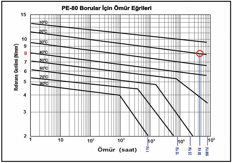

328 327
329 328
330 2- Saha Montajı 2- Field Applications 2.1- Depolama ve Taşıma Depolama PE ürünleri depolarken bazı önlemler alınmak zorundadır. Önerilen en fazla yükseklik 1 m olup, yığılmış borular için dağılmaya karşı önlem alınmalıdır. Kangal borular en iyi silo olarak depolanabilirler. Kangallar bu silolardan birer birer, dengeyi bozmadan alınabilir. Düz borular sıralar halinde üst üste depolanabilirler. Borular birbirleriyle açı yapmamalı, alt sıra ise yanal harekete karşı sabitlenmelidir. Yan dikme destekler, boruların ucundan 600 mm kadar sonra başlamalı, en az 100 mm eninde olmalı ve 1.5 m den fazla aralıklı olmamalıdır Storage and Handling Storage Some precautions have to be taken when storing PE products. Maximum recommended storage height is 1 m, and the pipes should be secured to prevent bundles splitting open. Coiled pipes are best stored in silo packs. Individual coils can be taken from the silo pack without disturbing the stability. Straight pipes can be stacked in rows, laid straight and not crossed or entangled with another. The base row must be secured by blocking any possibility for sideways movement. The side support blocks must begin at about 600 mm from each end, be at least 100 mm wide and be spaced no more than 1.5 meters. Boruların üstüste depolanması Borular yatay bir düzlemde depolanmalı ve keskin objelerle temas etmemelidir. PE fitingler kapalı bir alanda, naylon ambalajlar içinde depolanmalıdır. Boru ve fitinglerin toprak, pislik, atık su veya solventler ile teması önlenmelidir Taşıma Donma noktası civarı ve daha düşük sıcaklıklarda, PE sertleşerek darbe ve gerilimlere karşı daha dirençsiz olur. Bundan dolayı, borular yere düşürülmemeli, alet veya diğer malzemelerle darbe görmemeli, yüksek hızda yerde sürüklenmemelidir. El testeresi ile keserken, boru iki tarafından da desteklenmelidir. Düşük sıcaklıklarda keserken gerilime maruz kaldığı takdirde borular kırılabilir. PE boruların bükme yarıçapı (Rmin), boru çapına ve ortam sıcaklığına göre farklılık gösterir. Stacking of pipes The pipes must be stored on a level floor and not be in contact with sharp objects. PE fittings must be stored in a closed place and within nylon bags on site. Precautions against contamination of pipes and fittings, by soil, dirt, waste water or solvents should be taken Handling At temperatures near and below freezing point, PE becomes stiffer and more vulnerable to impacts and stresses. So, care should be taken not to drop pipe, make impacts on it with tools or other objects, or not to drag at speeds where bouncing can harm the pipe. Pipes should be supported at both sides when cutting with a handsaw. At low temperatures, the pipes may fracture if bending stress is present while cutting. Bending radius of PE pipes (Rmin) vary with their diameter and ambient temperature. Sıcaklık 20oC 10oC 5oC Boru ekseninde Minimum Bükme Yarıçapı (Do= dış çap) 20xDo 35xDo 50xDo Temperature 20oC 10oC 5oC Minimum Bending Radius at Pipe Axis (Do= outer diameter) 20xDo 35xDo 50xDo 329
331 Boruların taşınacağı vasıtaların kasaları, tam boyu alacak kadar uzun olmalıdır. Vasıta üzerinden borular alınırken, geniş kayışlarla vinç veya forklift kullanılmalıdır. Birim alana daha fazla yük bineceğinden dolayı kaldırmak için halat veya zincir kullanılmamalıdır. Hiçbir şekilde, borular ve fitingler vasıta üstünden yere atılmamalıdır Mesnetleme Açıkta (havada) mesnetlenmiş döşeme Mesnetleme aralıkları, borunun ebadına, özelliklerine, akışkan yoğunluğuna, ortam sıcaklığına ve serim hattına bağlıdır. Genellikle aralıklı mesnetler kullanılmasına rağmen, küçük çaplar için (ör mm) kesintisiz mesnetler gerekebilir. Mesnet semerleri, borunun alt yüzeyinde en az 120 derece yataklama yapmalı ve en az boru çapının yarısı kadar geniş olmalıdır. Mesnet kenarları boruyu korumak için keskin kenarlı olmamalıdır. Bu kriterler ışığında, örneğin, U-cıvatalar PE boru tespiti için uygun değildir. Vehicles for transportation should have beds that are long enough to support the whole length of pipes. When unloading the vehicle on site, silo packs and palletized items should be taken off the vehicle by wide web slings or by a forklift. Wire ropes and chains should not be used as they can damage the pipes. In no cases should the pipes and fittings be rolled or pushed off the vehicle to the ground Supporting Above Grade Supporting The support distances depend on the physical properties of laid pipe, the pipe size, the density of the flow media, operating temperature and piping layout. Applications usually involve non-continuous supports, but for small diameters (e.g mm) continuous supports may be necessary. Supports for pipes must cradle at least 120 degrees of the lower part of the pipes, and have a width of minimum 0.5 pipe diameter. The support edges must be rounded, free of sharp edges to prevent cutting into pipes. In the light of these criteria, for example, U-bolts are not suitable for PE pipe supporting. PE borunun mesnetlenmesi / Supporting of PE pipes o Yatak Mesnet aralığı için şekil / Figure for support spacing 330
)1/4] / 100 Açıklamalar; L: Mesnet aralığı (m) E: Elastisite modülü (MPa) I: Borunun atalet momenti (cm4) d: izin")
332 Mesnet aralıkları, mesnetler arası izin verilen çökmeye, boru malzemesine ve boyutlarına, içerideki akışkana ve sıcaklığa bağlıdır. Mesnet aralıkları aşağıdaki formülden hesaplanabilir: L = [(3840xExIxd / (5(Wp+Wf))1/4] / 100 Açıklamalar; L: Mesnet aralığı (m) E: Elastisite modülü (MPa) I: Borunun atalet momenti (cm4) d: izin verilen çökme (cm) Wp: Borunun birim ağırlığı (kg/cm) Wf: Akışkanın birim ağırlığı (kg/cm) The effective spans are related to allowed collapse value between the effective spans, the material and size of the pipe, the inner fluid and the temperature. The values of the effective spans can be calculated with the below formula: L = [(3840xExIxd / (5(Wp+Wf))1/4] / 100 The explanations; L: The effective span (m) E: The elasticity modüle (MPa) I: The inertial momentum of the pipe d: The allowed collapse value Wp: The unit weight of the pipe Wf: The unit weight of the fluid Uzun süreli kullanımlar için, PE100 boruların tipik E değerleri tablosu: For long-term usage, typical E values for PE100 pipes are shown in the table below: Sıcaklık/Temp. ( o C) E (Mpa) Toprağa gömerek döşeme Toprağa boru döşemek; kaz, boru döşe, üstünü kapat türü bir yaklaşımdan çok daha ciddi ve zor bir iştir. Bu işlem ciddi mühendislik yaklaşımları gerektirir. Burada detayına inmeğe çalışmak çok anlamsız olacaktır; ancak, temel kavramlardan söz edilecektir. Burada söz edilen konular temel bir rehber niteliğinde olup, gerçek işlemler uzman mühendisler tarafından, her işin gerektirdiği farklı uygulama yöntemlerine karar verilerek yapılmalıdır. Boru Gömmeye Dair Malzeme ve İşlem Terminolojisi Terminolojide, malzemelerin bulunduğu yere veya işlevlerine göre terimler yer almaktadır As Buried in Soil Burying pipes in soil is in no ways simple as it looks dig, lay the pipes, then cover with soil. Serious engineering concepts are involved with the process. It will be meaningless here, to introduce these concepts with detail; however, basics in considerations will be given. Please remember that these topics given here are for guide purposes only; and burying pipes in soil should be carried out by professional engineers. Terminology of Pipe Embedment Materials The materials enveloping a buried pipe are generally identified, as shown by their function or location (see Figure below). Boru Gömme Terminolojisine Dair Şekil Figure for Terminology of Pipe Embedment Materials 331
333 Gömme Temeli Kazılan hendek dibi yeterli sağlamlıkta bir zemin oluşturmuyor ise gereklidir. Birincil ve İkincil Dolgular Hendek dibinden itibaren, borunun en az 15 cm üstüne çıkacak şekilde yapılan toprak dolgudur. Borunun yüklere dayanımı ve oynamaya karşı direncini bu dolgunun kalitesi belirler. Yataklama Hendek zeminini istenen düz seviyede yapma işlemidir. Birincil Dolgu Borunun alt bölümünü çevreleyen ve boru çapının %75 ine kadar yükselen dolgudur. Bu malzemenin kalitesi ve uygulama tekniği, dolgulama işleminin en önemli aşamasıdır. İkincil Dolgu Bu dolgunun temel amacı, üstten gelen yüklerin dağıtılması ve son dolguda olabilecek oynamalara karşı boruyu korumasıdır. Yeraltı sularının boru seviyesinin üstüne çıkabileceği durumlarda, ikincil dolgu birincil dolgunun evsaf olarak devamı olmak durumundadır. Minimum hendek genişliği, çalışma bölgesi şartları ve gömme malzemelerinin evsafına bağlıdır. Son Dolgu Son dolgu işlev itibarı ile bir gömme malzemesi olmadığından, yapısı ve basılmasının boruya olan etkisi fazla değildir. Ancak, sert bir son dolgu da boruya binecek olan üst yükleri azaltacaktır. Boruya gelebilecek hasarları önlemek açısından, son dolgu malzemesinde iri kayalar, organik malzemeler ve molozlar bulunmamalıdır. Son dolgunun malzeme ve sıkıştırma işlemleri yol, kaldırım, vb. yapım kurallarına uyumlu olmalıdır. PE Boru İçin Montaj Yönergeleri İlgili mühendis, çalışma yeri ve yüzey altı şartlarını ve uygulama hedeflerini gözönünde bulundurarak borunun ihtiyacı olan takviye derecesini saptamak durumundadır. Uygulama derinliğinin fazla olması, toprağın tutuculuğunun yetersiz olması, yüzey veya yol yüklerinin fazla olması, boru et kalınlığının ince olması gibi durumlarda özel montaj yönergesinin hazırlanması gereklidir. Aslında çoğu zaman aşağıda belirtilen genel uygulama yöntemlerinin de yeterli olduğu bir gerçektir. Bu uygulamalar, tipik olarak, fazla derine döşenmedğinden üstünde aşırı toprak yükü olmayan, yeterince dayanıklı basınçlı boruların olduğu hallerdedir. Bu uygulamaların yol kestiği bazı kısımlarında özel mühendislik dikkati isteyen durumlar olabilmektedir. Basınçlı Borular İçin Basitleştirilmiş Uygulama Yöntemleri (Küçük çaplı borular çoğu zaman yüzeye yakın döşenip yeterli dayanıklıkta olduklarından, özel bir çökme incelemesi gerektirmemektedirler). Çoğu zaman, aşağıda belirtilen basit adımlar başarılı bir uygulama için yeterlidir. Bu adımlar, şu şartların sağlanması halinde geçerlidir: 1. Boru çapı 600 mm veya daha az Foundation - A foundation is required only when the native trench bottom does not provide a firm working platform for placement of the pipe bedding material. Initial Backfill - This is the critical zone of embedment soil surrounding the pipe from the foundation to at least 15 cm over the pipe. The pipe s ability to support loads and resist deflection is determined by the quality of the embedment material and the quality of its placement. The bedding, haunching, primary, and secondary zones are within the initial backfill zone. Bedding - In addition to bringing trench bottom to required level, the bedding levels out any irregularities and ensures uniform support along the length of the pipe. Haunching - The backfill under the lower half of the pipe distributes the combined loadings. The nature of the haunching material and its placement are the most important factors in limiting the deformation of PE pipe. Primary Initial Backfill - This zone of backfill provides the support against lateral pipe deformation. To ensure such support is available, this zone should extend from trench level up to at least 75 percent of the pipe diameter. Under some conditions, such as when the pipe will be permanently below the ground water table, the primary initial backfill should extend to at least 15 cm over the pipe. Secondary Initial Backfill - The basic function of the material in this zone is to distribute overhead loads and to protect the pipe from any adverse effects of the placement of the final backfill. When groundwater levels are expected to reach above the pipe, the secondary initial backfill should be a continuation of the primary initial backfill in order to provide optimum pipe support. Minimum trench width will depend on site conditions and embedment materials. Final Backfill - As the final backfill is not an embedment material, its nature and quality of compaction has a less effect on the flexible pipe. However, arching and thus a load reduction on the pipe is promoted by a stiff backfill. To preclude the possibility of impact or concentrated loadings on the pipe, both during and after backfilling, the final backfill should be free of large rocks, organic material, and debris. The material and compaction requirements for the final backfill should reflect good construction applications and satisfy local ordinances and sidewalk, road building, or other applicable regulations. Installation Guidelines for PE Pipe The engineer must evaluate the site conditions, the subsurface conditions, and the application objectives to determine the extent of support the pipe may need from the surrounding soil. Where the pipe burial depth is relatively deep, where subsurface soil conditions are not supportive of pipe, or where surface loads or live loads are present, or where the pipe DR is high, it is of importance that the engineer prepares a specific installation specification. On the other hand, there are many applications that meet the criterion below for using Simplified Installation Guidelines. Typically these lines contain pressure pipes installed at shallow depths which are sufficiently stiff to resist the minimal earth load. In some cases a pipeline may contain sections that require specific engineering such as a section that crosses a road. 332
334 2. SDR (Standard Dimension Ratio - Dış çapın et kalınlığına oranı) 26 veya daha az 3. Dolgu yüksekliği 0.75 m ve 5 m arasında 4. Yeraltı suyu yüksekliği her zaman yüzeyden 60 cm den daha aşağıda 5. Boru döşenmesi oynamayan toprakta. Oynamayan topraktan kasıt, toprağın dik veya dike yakın derecede kesilmesi halinde toprağın akmadan durabilmesi halidir. Toprağın yüksek taşıma dayanımına da sahip olması gereklidir. Aşağıdaki uygulamalar, genel anlamda olup işin erbabı bir mühendisin yaptığı uygulamaları kontrol amacı ile kullanılmamalıdır. Basitleştirilmiş Montaj Aşamaları Hendek Kazma Hendek çökmelerinin her toprakta olabilme ve çalışanların sağlık veya hayatına tehlike oluşturma durumu vardır. Takviyelendirilmemiş kazılarda, hendek kenarları güvenli bir açıda tutulmalı ve yerel iş güvenliği kurallarına uyulmalıdır. Tüm desteklemeler boru seviyesinin üstünde yer almalıdır. Kazılan hendek bölümlerinin uzunlukları hesaplanırken, boru aşağı sarkıtılırken önerilen asgari bükme yarıçapından daha keskin bükümler olmayacak boyda kazılmasına dikkat edilmelidir. Hendek genişliği 600 mm çaptan daha küçük borular için boru çapı mm; daha büyük çaplar için boru çapı mm kadar olmalıdır. Boru çapı ve döşeme derinliğine göre önerilen hendek boyları arkadaki tabloda verilmektedir: Simplified Installation Guidelines for Pressure Pipe (Small diameter pressure pipes usually have adequate stiffness and are usually installed in such shallow depths that it is unnecessary to make an internal inspection of the pipe for deflection.) A quality job can be achieved for most installations following the simple steps that are listed below. These guidelines apply where the following conditions are met: 1. Pipe Diameter of 600 mm or less 2. SDR (Std. Dimension Ratio) equal to or less than Depth of Cover between 0.75 m and 5 m. 4. Groundwater elevation never higher than 60 cm below the surface 5. The route of the pipeline is through stable soil Stable soil is an arbitrary definition referring to soil that can be cut vertically or nearly vertically without significant sloughing, or soil that is granular but dry (or de-watered) that can stand vertical to at least the height of the pipe. These soils must also possess good bearing strength. Examples of soils that normally do not possess adequate stability for this method are mucky, organic, or loose and wet soils. Where the above conditions are met, installation specifications from the following steps can be written. It should be made sure that all state and local safety regulations are met. The following are general guidelines for the installation of PE pipe. Other satisfactory methods or specifications may be available. The information below should not be substituted for the judgment of a professional engineer in achieving specific requirements. Simplified Step-by-Step Installation Trenching Trench collapses can occur in any soil and are dangerous for worker health, or lives. In unsupported excavations, proper attention should be paid to sloping the trench wall to a safe angle; local codes should be consulted. All trench shoring and bracing must be kept above the pipe. (If this is not possible, consult the more detailed installation recommendations.) The length of open trench required for fused pipe sections should be such that bending and lowering the pipe into the ditch does not exceed the manufacturer s minimum recommended bend radius. The trench width at pipe grade should be equal to the pipe outer diameter (OD) plus 300 mm for pipes with OD 600 mm or less; and OD plus 600 mm for pipes with OD greater than 600 mm. Table for suggested trench lengths with regard to Pipe OD and trench depth: 333
335 Asgari Hendek Boyu (m) / Min. Length of Trench (m) Boru Çapı (mm) Sudan korumak Güvenli ve uygun yapım için, hendekteki suyun borunun ağız altı seviyesinden daha aşağıda tutulması ve boruya su girmemesi gereklidir. Bu, suyun toplanacağı derin kuyular kazmak veya pompa ile suyu devamlı boşaltmak şeklinde olabilir. Yataklama Hendek zemini problemsiz olarak açılıp düzleştirilebiliyorsa, basınçlı borular doğrudan hendek zeminine yerleştirilebilir. Hendek zemini hafif dalgalı olabilir; ancak, boru zemine tam oturmalı, boşluk veya tümsek üstünde kalmamalıdır. Toprağın kayasız veya kazı sırasında güzelce ufalandığı durumlarda, kazı toprağı zeminde yataklamak için de kullanılabilir. Hendek dibi kayalıksa, taban üstüne cm kadar dolgu yapılabilir. Dolgu malzemesi serbestçe akabilen çakıl, kum, çamurlu veya killi kum olabilir. Ancak, bu malzemelerin içindeki taşlar 1 cm den daha küçük olmalıdır. Bu malzemelerden 15 cm kadar yükseklikte sıkıştırılmış zemin, boruya güzel bir yatak oluşturur. Boruyu Hendeğe Yerleştirmek 200 mm çapa ve kabaca 9 kg/m ağırlığa kadar olan borular, hendeğe el ile döşenebilir. Daha büyük borular için mutlaka uygun taşıma ve kaldırıp indirme ekipmanına gerek vardır. Borular hiçbir şekilde hendeğe yuvarlanmamalı, itilmemeli ve atılmamalıdır. Hendek çevresinde insanlar olduğu zaman mutlaka gerekli güvenlik önlemleri alınmalıdır. Güneşte ısınıp genleşmiş bir boru hendeğe koyulduğunda soğuyup büzülecektir. Bu soğuma çekmesi, boruların mekanik birleşme bağlantılarından çıkmasına sebep olabilir. Bundan dolayı, borular hendeğe indirildikten sonra soğuması için beklenmeli, sonra mekanik bağlantılar yapılmalıdır. Boruyu Kavisli Döşemek Flanş ve fitingli bağlantılar borudan daha sert olduğu için, kavis içinde böyle bir bağlantı varsa, bu bağlantının hem öncesi hem sonrasında 5 boru çapına kadar olan mesafede asgari büküm yarıçapı boru çapının 100 katı olmalıdır. Boruyu kavisli hendek içine yerleştirirken ve birincil dolgu yapılırken, boru kavisini korumak için geçici destekler kullanılması gerekebilir. Son dolgudan önce bu destekler kaldırlımalı, oluşan boşluklara yine birincil dolgu malzemesinden dolgu yapılmalıdır. Hendek Derinliği (m)/ Depth of Trench (m) Nom. Pipe Size (mm) De-watering For safe and proper construction the groundwater level in the trench should be kept below the pipe invert. This can be done by deep wells, well points or sump pumps placed in the trench. Bedding Pressure pipes may be installed directly on the prepared trench bottom if the trench bottom soil can be cut and graded without difficulty. For pressure pipe, the trench bottom may undulate, but must support the pipe smoothly and be free of ridges, hollows, and lumps. In other situations, bedding may be prepared from the excavated material if it is rock free and well broken up during excavation. The trench bottom should be relatively smooth and free of rock. When rocks or large stones are met which may cause point loading on the pipe, they should be removed and the trench bottom padded with cm of bedding material. Bedding should consist of free-flowing material such as gravel, sand, silty sand, or clayey sand that is free of stones or hard particles larger than 1 cm. A mat of at least 15 cm of compacted embedment material will provide satisfactory bedding. Placing Pipe in Trench PE pressure pipe up to about 200 mm diameter and weighing roughly 9 kg/m or less can usually be hand-placed in the trench. Heavier, larger diameter pipe will require equipment to lift, move, and lower the pipe into the trench. Pipe must not be dumped, dropped, pushed, or rolled into the trench. Proper safety precautions must be taken whenever people are in or near the trench. Placing pipe that has been in direct sunlight in a cooler trench will result in thermal contraction of the pipe s length. This contraction can generate forces which could result in pull-out of couplings. Pipe should be allowed to cool before making connections to an anchored joint, flange, or a fitting that requires protection against excessive pull-out forces. Installation of Pipe in Curves Since fittings and flange connections are rigid compared to the pipe; when a fitting or flange connection is present in the bend, the minimum bend radius should be 100 times the pipe s outside diameter (OD). The bend radius should be limited to 100 x OD for a distance of about 5 times the pipe diameter on either side of the fitting location. Field bending involves excavating the trench to the desired bend radius, then sweeping or pulling the pipe string into the required bend and placing it in the trench. Temporary restraints may be required to bend the pipe, and to maintain the bend while placing the pipe in the trench and placing initial backfill. Temporary blocks or restraints must be removed before installing final backfill, and any voids must be filled with compacted initial backfill material. Caution: Considerable force may be required to field bend the pipe, and the pipe may spring back forcibly if the restraints slip or are inadvertently released while bending. Related safety precautions should be applied during field bending. 334
336 Dikkat: Boruyu kavislendirmek için yüksek güç gerekebilir, geçici desteklerden borunun kurtulması halinde tehlikeli geri yaylanma olabilir. Böyle durumlarda mutlaka ilgili güvenlik önlemleri alınmalıdır. Birincil Dolgu Birincil dolgu malzemesi, döşenmiş boruyu yerinden oynatmayacak şekilde yerine konmalı ve sıkıştırılmalıdır. Bu sırada, malzemenin borunun altına tamamen girdiği ve borunun alt kısmını güzelce sarmaladığı kontrol edilmelidir. Bu işlem için titreşimli kompaktörler, darbeli kompaktörlerden daha uygundur. PE Borudan Farklı Malzemeden Boru Veya Fitinge Contalı Geçiş PE boru kaynakla birleştirildiği zaman pratikte eksiz bir boru niteliğinde olmaktadır. Boru basınçlandırıldığında, iki farklı iç kuvvet altında kalır. 1- Büküm veya boru sonlarındaki itme kuvveti boruya eksenel çekme gerilimi olarak yansır, 2- İç basınçtan dolayı çevresel gerilim oluşur. Eksenel gerilim, borunun boyunu uzatmaya, çevresel gerilim de çapı genişletmeye, genişletirken de Poisson Oranı na göre boyu kısaltmaya çalışır. Tamamen PE olan bir sistemde bu etkenler birbirlerini hemen hemen yok ederler. Sonuç olarak, gömülmüş bir PE sistem kendi kendini tutar ve itmeye karşı önlem almak gerekmez. Ancak; PE boru, başka bir malzemeye, sabitlenmemiş contalı elemanlarla bağlandığı zaman farklı bir durum oluşur. Eksenel kuvvet oluşmayabilir. Bu durumda, genleşen çap boydan kısalmaya yol açabilir ve boru ek yerinden kurtulabilir. Genellikle, böyle bir geçişin olduğu hallerde PE borunun uçlarını sabitlemek gerekir. Şayet contalı eleman sabitlenmişse, boruyu ayrıca sabitlemeye gerek yoktur. PE Fitinglerin Gömülmesi Kaynaklanmış PE boru ve fitings, tek parça olma özelliğindedir. Dolayısı ile basınç itmesine karşı ayrıca sabitlemek gerekmez. Muflu bağlantılarda ise ek yeri mutlaka ayrılmaya karşı sabitlenmelidir. Elastik şekil değişimi, ısıl genleşme/büzülmeler vs. dolayı olan hareketler PE boruya zararlı değildir; ancak, vana veya benzeri armatürlerin eklenmesinden dolayı olacak hareketler boruya aşırı yükler getirebilir. Çoğu zaman, uygun dolgulama aşırı yükleri engeller. Genel fitings, dirsek ve Te ayrımlar için boru ile aynı dolgu malzemesi yeterlidir. Servis bağlantıları da PE malzemeden yapılırsa özel sıkıştırma gerekmez. Servis bağlantları taşıt yolu altında yapılmışsa, buralarda %95 Standart Proctor yoğunluğunda sıkıştırma gereklidir. Su ve yangından koruma sistemlerinde, ana hattan vana ve hidrantlara ayrımlarda redüksiyonlu Te bağlantılar sıkça kullanılmaktadır. Aşağıdaki şekilde, böyle uygulamalar için çeşitli sabitleme yöntemleri gösterilmektedir. Te ve dirseklerde çevresel sıkıştırma yapmak yerine çimentolu kum ile sağlamlaştırmak çok daha kolaydır. Haunching Haunching material must be carefully placed and compacted so as not to disturb the pipe from its line and grade while ensuring that it is in firm and intimate contact with the entire bottom surface of the pipe. Usually a vibratory compactor has less tendency to disturb the pipe than an impact tamper. Transition from PE Pressure Pipe to Gasket Jointed Pipe The heat fusion joint used for PE pipe creates an essentially continuous length of pipe. When the pipe is pressurized two significant internal forces are present in the pipe. 1- End thrust from bends or end caps is transmitted through the pipe as a longitudinal force. 2- Circumferential stress occurs due to the internal pressure. The longitudinal force tends to grow the pipe length while the circumferential thrust expands the diameter and tends to contract the pipe s length in proportion to Poisson s Ratio. In an all PE pipe system, the length effects from these two forces tend to cancel each other out. As a result, buried PE pipes are self-restrained and require no blocking against thrust. However, a different situation occurs when PE pipe transitions to a different type of pipe material that is joined by nonrestrained gasket joints. The longitudinal force may no longer be present. The result is that circumferential expansion is now unbalanced and will cause contraction of the PE pipe. This contraction can result in pulling apart of gasket joints in line with the PE pipe. Generally, it is necessary to anchor the ends of a PE pipeline that makes a transition into an unrestrained gasket jointed pipe system. If the gasket joints are restrained, anchoring is unnecessary. Proper Burial of Fabricated PE Fittings Heat fused PE pipe and fittings are monolithic structures, which do not require thrust blocks to restrain the longitudinal loads resulting from pipe pressurization. Since fittings are part of the monolithic structure no thrust blocks are needed to keep the fittings from separating from the PE pipe. However; bell and spigot piping systems must have thrust blocks or restrained joints to prevent separation of pipe from fittings when there is a change of direction. Pipe movement due to elastic deformation, thermal expansion/ contraction, etc. is not harmful to PE pipe, but pipe movement or the addition of valves or other elements used with PE pipe systems can cause excessive loads. In most cases, proper backfill prevents excessive loads. Common fittings, elbows and equal tees normally require the same backfill as the pipe. When service connections are made from PE water mains, no special compaction is required. When service connections are made under an active roadway, 95% Standard Proctor density is normally required around the pipe and the service connection. In water systems and fire protection piping systems, reducing tees are frequently used to connect from the main to valves and hydrants. Figure below shows the use of concrete support pads, thrust blocks on hydrants, self restrained PE mechanical joint adapters and sand stabilized with cement around the bend and reducing tee. While no true thrust blocks are on the PE pipe or fittings in this arrangement, the sand stabilized with cement provides proper support for the reducing tee. Stabilizing sand with cement or flowable filling material is easier than trying to compact around the fittings. 335
337 PE fitinglerin gömülmesine dair çeşitli örnekler Figure for samples of PE fittings burial 336
338 Boru Gömme Gömme malzemesi çakıl, kum, veya kaba parçacıklar içeren çamurlu / killi kum olabilir. Parça büyüklüğü mm borular için 10 mm, mm borular için 20 mm, daha büyükler için 25 mm den küçük olmalıdır. Gömme malzemesi 15 cm den az katlar halinde yapılmalı, mekanik bir sıkıştırıcı ile sıkıştırıldıktan sonra bir üst kata geçilmelidir. Kaçak Testi Kaçak testleri gerekiyorsa, Bölüm 2.6 da açıklanan şekilde gerçekleştirilmelidir. Hendek Son Dolgusu Son dolguda kazıdan çıkan malzeme kullanılabilir, ama uygun olmayan malzemelerin ayıklanması gereklidir (iri kil parçaları, organik malzemeler, 20 cm den büyük kayalar gibi). Borunun taşıt yolu altından geçtiği hallerde, son dolgu da kademeli olarak, her kademe %95 Standart Proctor yoğunluğunda sıkıştırılarak yapılmalıdır. Son dolgu boru montajı bittikten hemen sonra yapılmalıdır. Böylece boru, olası darbelerden, su basması sebebi ile borunun yerinden oynamasından veya soğuk havalarda dolgu malzemesinin donmasından korunmuş olacaktır Su altında döşeme Su altı uygulamaları için PE boru son derece uygun bir malzemedir. Ana sebebi korozyona karşı dayanıklılık olsa bile, aşağıda sayılan diğer avantajları da çok önemlidir: PE Hafiftir Belli bir çap ve performans şartlarında, kullanılacak olan PE boru beton borudan %10, çelik borudan %50 daha hafif olduğundan taşıma ve montajda kolaylık sağlar. PE Yüzer PE yoğunluğu tatlı suyun %96sı, deniz suyunun ise %94ü kadar olduğundan, içi su dolu olsa bile su üstünde kalmaktadır. Uzun boylar kıyıda birleştirilip hedefe kadar su üstünde yüzdürülerek taşınabilir, yerinde ağırlık eklenerek dibe indirilebilir. Kaynaklı Birleşimler Alın kaynağı metodu ile mekanik bağlantılara gerek kalmadan PE boruları boy boy birbirine eklenebilir. Kaynatılan yerler borunun kendisi kadar sağlamdır ve mekanik bağlantılarda olan sızdırma riski bulunmamaktadır. PE Esnektir PE boruyu suya yavaş yavaş indirerek taban yüzeyine uyum göstererek oturması mümkündür. PE Yumuşaktır Yüksek şekil değiştirme özelliğinden dolayı, su altı dalga ve akıntılarının yarattığı değişken yüklere başarı ile karşı koyar, aynı sebeplerden dolayı olan dip yüzey değişikliklerine borunun uyumlu olmasını sağlar. PE borular su dolu olduğu halde yüzdüklerinden, karada veya bir yüzer platform üzerinde iken ağırlıklar eklenmelidir. Boru hattı yüzdürülerek gerekli yere çekilir ve batırılır. Tipik ağırlık tasarımında, boru hava ile doluyken (uçları kapatılmış) ağırlıklarla yüzebilmeli, su doldurulunca da batabilmelidir. Ağırlıkların fazla yapılması gerektiği hallerde, yüzdürmek için geçici bağlanmış varillerden faydalanılabilir. Kıyıda iken, ağırlıkların boruya bağlandığı yer bir rampa Pipe Embedment The embedment material should be a coarse grained soil, such as gravel or sand, or a coarse grained soil containing fines, such as a silty sand or clayey sand. The particle size should not exceed 10 mm for mm pipe, 20 mm for mm pipe and 25 mm for all other sizes. Where the embedment is angular, crushed stone may be placed around the pipe by dumping and slicing with a shovel. Where the embedment is naturally occurring gravels, sands and mixtures with fines, the embedment should be placed in lifts, less than 15 cm in thickness, and then tamped. Tamping should be accomplished by using a mechanical tamper (600 kn-m/m3). Leak Testing If a leak test is required, it should be conducted in accordance with the procedure in Section 2.6 after the embedment material is placed. Trench Backfill The final backfill may consist of the excavated material, but it must be free from unsuitable matter such as large lumps of clay, organic material or Stones larger than 20 cm, or construction debris. Where the pipe is located beneath a road, the final backfill should be done in lifts and be compacted to 95 percent Standard Proctor Density. Backfilling should be done as soon as possible after pipe placement and assembly. This prevents the pipe from being dislocated by cave-ins, protects the pipe from external damage, eliminates pipe lifting due to flooding of open trench and in very cold weather, reduces the possibility of backfill material becoming frozen. In most cases, compaction will be required for all material placed in the trench from 15 cm below the pipe to at least 15 cm above it Underwater Application Polyethylene (PE) piping is very beneficial to be used for various underwater applications. Immunity to corrosion is the major reason for choosing PE. However, other beneficial features, listed below, also contribute to the usage of PE in underwater applications: PE Has Low weight For a given pipe diameter and equivalent performance requirements, the weight of PE pipe is around 10% of the weight of concrete pipe and less than 50% of iron. So handling is easier. PE is buoyant Because PE s density is about 96% of fresh water, and about 94% of that for sea water, PE pipe floats even if it is filled with water. Long lengths can be assembled on shore and then be floated to its target location, and then ballasted to keep it anchored at its final submerged location. Welded joints Using butt fusion method, continuous lengths of PE pipe can be welded without using mechanical joining elements. The welded joints are as strong as the pipe, and they eliminate the risk of leakages from mechanical joints. PE is Flexible It is possible to sink the PE pipe gradually and to adapt to the natural contours of underwater surfaces. This means that the flexible pipeline can normally be placed directly on the natural bottom without any trenching or other form of preparation of continuous level support. PE is Ductile Because of its high deformation capacity, PE piping can safely compensate for variable external forces due to waves and currents. PE piping can also safely shift or bend to adjust itself to altered bedding that can result by the strong waves and currents. Since the PE pipes will float even when filled with water, ballast weights must be installed, either on shore or on barges over water. The pipeline is then floated into location and sunk into its position. Typical ballast weight design allows an air-filled 337
339 ile suya kavuşabilir. Bu sayede, ağırlıklı borular suya kaydırılabilir. Su üstünde de, yüzer platform vinçleri ağırlıklı boruyu nakletme ve yerleştirmede kullanılabilirler. Boru hattı bir tekne ile veya halatlarla çekilerek yerine götürülür. Batırma sırasında pozisyonu bozulmasın diye geçici olarak sabitlemek mümkündür. Kıyı tarafından boruya su verilip diğer tarafındaki ucundan hava kontrollü bir şekilde tahliye edilerek borunun yavaşça suya batması sağlanır. Bu işlem sırasında her iki ucun da su seviyesinden yüksekte tutulması gereklidir. Hava tahliye hızı, suyun boruya dolma hızını kontrol eder. Suyun dolma hızının kontrolü, borunun aniden dolarak kırılmaya yol açacak bir büküme uğramasına engel olmak açısından çok önemlidir. Şayet boru su altında da toprağa gömülecekse, tüm hendek açma işlemi batırma işinden önce yapılmalıdır. Sualtı dolgusu küçük boyuta ufalanmış kayalardan oluşmalı, ek koruma gerekiyorsa bu dolgunun üstüne kaya veya beton parçaları yerleştirilmelidir. Sualtı Uygulamaları İçin Temel Dizayn ve Montaj Aşamaları: Hemen tüm sualtı uygulamalarında, aşağıda belirtilen aşamalar geçerlidir: 1. Uygun boru çapı belirlenmesi Akışkan cinsi, debi ve boru hattının uzunluğu esas alınarak hidrolik hesaplar yapılmalı ve asgari boru iç çapı belirlenmelidir. 2. Montaj ve çalışma şartları gözönünde bulundurularak uygun Boyut Oranı (DR-Dimension Ratio) hesaplanması Bu işlem, borunun öngörülen sıcaklık ve basınç şartlarında güvenli hizmet vermesi açısından önemli ve gereklidir. Bu konuda bilgi Bölüm 3.1 de verilmiştir. Ayrı bir emniyet katsayısı olarak, çalışma sıcaklığını borunun iç veya dış ortamından hangisi yüksekse o değeri almak önerilir. Seçilen borunun basınç değerinin, çalışmada olabilecek koç darbelerini de karşıladığı kontrol edilmelidir. Koç darbeleri pompaya yol verme veya durdurma sırasında olabilmektedir. Bu konudan da Bölüm 3.2 de bahsedilmiştir. 3. Boruyu batırmak için gerekli ağırlık ve montaj aralıklarının hesaplanması 3.1. Boruyu hedefe ne yüzerek, ne batarak durumda taşımak için gerekli ağırlık belirlenir. Suyun içindeki bir borudaki kaldırma kuvveti, boru ve içindekinin ağırlığı ile borunun taşırdığı suyun ağırlığı arasındaki fark kadardır. Bu bağlantı şu şekilde ifade edilebilir: F = [Wboru + Wmadde] Wtaşma F = birim metredeki kaldırma kuvveti, kg/m boru Wboru = borunun birim ağırlığı, kg/m boru Wmadde = boru içindeki maddenin birim ağırlığı, kg/m boru pipeline to float with ballast weights attached, if both ends of the pipeline are capped. Temporary floats such as barrels attached to the pipeline may be required to control sinking; if the line is designed with heavy ballast weights. On shore, ballast weight installation can be eased with a sliding ramp to slide ballasted pipe into the water. Over water, barge mounted cranes may be used to handle pipe with ballast weights. Once ballasted, the pipeline is moved into position with marine craft or pulled into position with cables. Temporary anchoring may be necessary to maintain position during sinking. Water is introduced from the shore end, and air is vented slowly from the other end. Water must not be allowed to run the full length of the pipe. The shore end should be raised slightly to create a u-bend of water that moves down the line as the line sinks. The floating air bleed end should also be above the water level to prevent water entry. Bleeding rate of air from the floating end controls the water entry rate. It is essential that sinking rate must be under control, so the pipe does not bend too tightly and kink. If the pipeline is to be buried inside the water bedding, all trench work must be done before sinking. Underwater backfill should be coarse soil such as crushed rock. If additional erosion protection is necessary, large stones or broken concrete may be placed over the initial backfill. Basic Design and Installation Steps for Underwater Applications: In almost all underwater applications, the design and installation of PE piping requires the following basic steps: 1. Selection of proper pipe diameter Pipe minimum inside diameter should be calculated by employing hydraulic calculations, dependant on the required flow rate and the pipe length. 2. Determination of proper pipe DR (Dimension Ratio - proper wall thickness) considering the installation and operating conditions This is necessary for the pipe to operate safely at the maximum design net internal pressure at the maximum proposed operating temperature. Information for determining the appropriate pipe DR is presented in Section 3.1. As an extra safety factor, it is of good practice to pressure rate the pipe for the maximum anticipated operating temperature of either the internal or external environment, whichever is higher. A check should also be made to make sure that the selected pipe pressure rating is also sufficient to resist any momentary pressure surges above normal operating pressure. Pressure surges can occur during pump start-ups or shut-downs. Guidance for selecting a PE pipe with sufficient surge pressure strength is also presented in Section Designing the weight and pitch of the ballast weights spacing that will be used to sink and then hold the pipe in position 3.1. The necessary weighting that is required to neither sink nor float condition (for transporting to the intended place before sinking) is determined. The buoyant force on a submerged PE pipe is equal to the sum of the weight of the pipe and its contents minus the weight of the water that the pipe displaces. This relationship can be expressed as: F = [Wpipe + Wcont] Wdispl F = buoyant force, kg/m of pipe Wpipe = weight of pipe, kg/m of pipe Wcont = weight of pipe contents, kg/m of pipe Wdispl = weight of water displaced by pipe, kg/m of pipe 3.2. Minimum weighting for the anchoring of a submerged pipe in its final position is determined. 338
340 Wtaşma = borunun taşırdığı suyun birim ağırlığı, kg/m boru 3.2. Batırılmış borunun tam tespiti için gerekli ağırlık hesaplanır. Çoğu durumda, (boru dipte su ile dolu halde iken) taşırdığı su ağırlığının %25 ila %50 si arasında bir ağırlık eklenmesi, borunun dipte tam tespiti için yeterlidir. Bu yüzdelerin düşük değerleri göl gibi sakin sularda yeterli iken akıntılı yerlerdeki haller için yüksek değerlere geçilmektedir. Dalga hareketinin en etkin olduğu kıyıya yakın yerlerde, boruyu gömmek sıkça yapılan bir uygulamadır. Hatırlanması gereken bir nokta; su altında yapılan bir dolgu ince parçacıklı kum veya toprak olduğu taktirde, dalga hareketlerinin dolguyu gevşek ve akışkan hale getirmesinden dolayı borunun yerinden çıkabileceğidir. Boruyu taşırdığı su ağırlığının en az %40 I kadar bir ağırlıkla desteklemek, bu duruma engel olabilir. Borular aşağıdaki farklı şekillerde batırılabilir: Gerekli ağırlıklar iki aşamada bağlanabilir: Batırılacağı yere kadar yüzmesine yetecek kadar ağırlık bağlanır, batırıldıktan sonra yerinde ek ağırlıklar eklenir. İkinci bir metod, tam ağırlıklar konulup batırılacağı yere kadar geçici dubalara bağlanarak yüzdürülür ve yerinde duba bağlantıları çözülerek boru batırılır. Üçüncü bir metod da, ağırlıkların boruya su üstündeki bir yüzen platformda bağlanarak (aşırı bükülmeden olabilecek kırılmalara dikkat ederek) suya bırakılması ve ilerlerken bu işlemin devam etmesidir İstenmeyen yüzme etkisi yaratmaması için boruda hava cebi kalmadığından emin olunmalıdır Boruya bağlanacak ağırlık miktarları ve bağlama aralıkları belirlenir. Ağırlıklar arası mesafenin hesabındaki kriterler, boruyu havada mesnetleme ile hemen hemen aynıdır. Her iki durumda da boru, yayılmış yük altındadır; su içinde buna ek olarak akıntı ve dalga etkilerine maruzdur. Esas amaç, borunun bu bileşik kuvvetler altında maruz kalacağı bükme gerilimleri ve şekil değiştirmenin güvenli sınırlar içinde kalmasıdır. Aşağıdaki tabloda, genelde uygulanan ağırlık aralıkları gösterilmektedir. Hava cebi kalması riskine karşı önlem olarak, havada mesnetlenme aralıklarından daha az aralıklarla ağırlıklar konulmaktadır. In most cases a weighting of 25 to 50% of the pipe displacement is enough to maintain a properly anchored submerged PE pipe after it has been filled with water. The lower values of weight have been found satisfactory in cases (like in lake crossings), where current and wave action are relatively mild, while the larger values of weight are used in sea installations where sea actions are stronger. Closer to the shore, where wave action is at its strongest, it is a common practice to protect the pipe by trenching. It should be noted that, when a trench is refilled with fine-grained soil, the buried pipe can sometimes float from the trench, resulting from the fluidization of the fill by strong wave action. This situation can be avoided by weighting the pipe to at least 40% of its displacement. Pipes can be submerged in different ways, such as; The attachment of the required ballast weights can be done in two steps: primary weighting is conducted so as to still allow the pipe to be floated into position, and then the additional required weights are added where required after the completion of the submerging of the pipe. Another way is to temporarily increase the pipe s buoyancy by employing empty tanks, or large blocks of rigid plastic foamed material that are then released, as the pipe is being submerged. A third method is to attach the required ballast weights onto the pipe from a barge from which the pipe is slid to the bottom by means of a sled that is designed to ensure that the bending of the pipe is below the buckling limit It should be made sure that no air is trapped in the pipes to facilitate unwanted buoyancy. A surge basin can be used in the system design, at a point before the pipe enters the water. Care should be taken that no high points are present in the pipe layout, where air pockets can occur Weights and spacings of the ballasts that are attached to the pipe is determined. The principles for determining the spacing between ballasts are almost the same as those for the support spacing criteria for aboveground suspended pipelines. In both cases the pipes are subject to a distributed loading in the case of submerged pipelines, by the combined effect of current, lift and wave actions. The objective of the design is to limit resultant pipe deflection so that the maximum bending stresses and strains are within safe limits. Listed in Table below, are commonly used ballast spacings. To satisfy the aim for preventing air entrapment, the spans in this table are somewhat shorter than for pipes that are suspended above ground. 339
341 Nominal Boru Çapı (mm) Takribi Aralık (m) Nominal Pipe Diameter (mm) Approximate Spacing (m) < >300 - < > Ağırlıkların tasarım ve yapımı; ağırlıklar tipik olarak betonarme olarak yapılır. Farklı şekillerde olabilirler, ancak, batırma sırasında burulmaya yol açmaması açısından daire, kare, altıgen gibi simetrik kesitler tercih edilir. Batırılmış boru belirgin akıntılar içinde kalacaksa, burulma hareketine önlem olarak tabanı düz olan ağırlık şekilleri tercih edilir. Ağırlıklar üst ve alt parçalardan oluşmalı ve birbirine tam bağlandığı zaman boru ile arasında ufak bir açıklık kalmalıdır. Bu açıklık, yumuşak boru ve sert ağırlık arasında boru güvenliği açısından araya konacak tampon malzemesi içindir. Tampon malzemesinin diğer bir işlevi de, sürtünme tabakası oluşturarak ağırlığın (özellikle batırma sırasında) boru üstünde kaymasını önlemektir. Tampon malzemeleri üstüste sarılmış 3 mm kalınlıkta lastik veya 6 mm kalınlıkta neopren levha gibi malzemeler olabilir. Tecrübeler göstermiştir ki, gelgit veya akıntıların çok olduğu deniz uygulamalarında, alt kısmı üst kısmından daha ağır olan ağırlıkl blokları daha avantajlı olmaktadır. Bu blokların üst ve alt kısımlarında korozyona dayanıklı (ör. paslanmaz çelik) kaldırma kulakları, cıvata-somun bulunmalıdır Design and construction of ballast weights; ballasts are typically made of reinforced concrete. Ballasts can be made in different shapes, although a symmetrical design such as round, square, or hexagonal is preferred to avoid twisting during submersion. Flat-bottomed ballasts are preferred if the submerged piping will be subjected to significant currents, tides or wave forces; because they help prevent torsional movement of the pipe. The ballasts should have a top and bottom section that; when mated, the resultant inside diameter is slightly larger than the outside diameter of the pipe. This slightly larger inside diameter is to allow the placement of a cushioning material to protect the softer PE pipe from being damaged by the hard ballast material. Another function of the cushioning is to provide frictional resistance that will help prevent the ballasts from sliding along the pipe during the submersion process. Some suggested cushioning materials can be several wraps of approximately 3 mm thick rubber sheet or approximately 6 mm thick neoprene sponge sheet. Additionally, experience has shown that in certain marine applications where tidal or current activities may be significant, an asymmetric ballast design in which the bottom portion of the ballast is heavier than the upper portion of the ballast is recommended. Suitable lifting lugs should be included in the top and bottom sections of the ballasts. The lugs and the tightening elements should be corrosion resistant (e.g. stainless steel). Ağırlık bloklarının tipik ağırlıkları aşağıdaki tabloda verilmiştir: Boru Dış Çapı (mm) Outside Diameter of Pipe (mm) Borudaki % Hava Miktarına Karşı Koymak Üzere Ağırlık Bloklarının Aralıkları Spacing of Ballast Weights To Overcome % Air (m) Typical properties of ballast weights are shown in the table below: Betonarme Blokların Takribi Ağırlıkları (kg) Approximate Weight of Concrete Block (kg) 10% 15% 20% Havada Tatlı Suda In Air In Fresh Water , , , , , , , , , , , , , ,

342 4. Boruları birleştirmek ve suya indirmek için uygun bir yer seçilmelidir. Bu yerin borunun daldırılacağı suyun kenarında olması ve kara taşıtlarıyla ulaşılabilmesi ilk istenen şeydir. Borunun suya doğru çekileceği zemin boruya hasar vermeyecek yapıda, kayalık ve molozlardan arınmış olmalıdır. Ağırlıklar bağlı olarak borunun suya çekilebilmesi için kıyıda uygun bir rampa yapılmalıdır. 5. Karadan suya geçiş bölgesini ve gerekiyorsa sualtı yataklamasını hazırlamak Daldırma işlemi başlamadan önce, kıyıdan suya geçiş bölgesinde, borunun su içinde ek koruma olmadan durabileceği yere kadar bir hendek kazmak gerekebilir. Bu hendek, boruyu gelgit ve dalga hareketlerinden, akıntılardan, sürüklenen buz parçalarından ve tekne trafiğinden koruyacak kadar derinlik ve uzunlukta olmalıdır. Bu bölgedeki gömme, denizin hırçınlaştığı zamanlarda dahi bozulmadan durabilecek yapıda olmalıdır. Boru koruma ve sabitleme, dolgu üstüne kaya parçaları cm yükseklikte döşenerek de takviye edilebilir. Genel olarak, boruyu yerleştirmek için dip taramasına gerek yoktur, zira ağırlık blokları boruyu zeminden biraz yüksekte tutmaktadır. Yine de, borunun altına değebilecek irilikteki taşlar var ise bunların borunun her tarafından 3 çap uzaklığa kadar temizlenmesi gereklidir. 6. Parça boruların kaynatılarak tek parça boru yapılması Borular kaynatılarak peşpeşe eklendikçe, boru ön tarafından çekilerek suya daha çok sokulur. Ağırlıklar, boru suya değmeden bağlanmalıdır. Eğer şartlar daha uygun oluyorsa, ağırlıklar suda yüzen bir platformda da bağlanıp boru ondan sonra suya indirilebilir. 7. Ağırlık bloklarının bağlanması Ağırlık bloklarının depolanma alanından boruya montaj yerine getirilmesi, borunun kaldırılarak blok alt parçasının borunun altına sürülmesi, blok üst parçasının üste konularak sıkıştırılması işlemleri için yeterli ve uygun sayıda kaldırma ve taşıma ekipmanı gerekmektedir. Bu Borunun ağırlık içindeki durumunu gösteren örnek resim Sample picture showing pipe in ballast weight 4. Choosing a suitable place for staging, joining and launching the pipe The site for staging, joining and launching the pipe should preferably be on land adjacent to the water in which the pipeline is to be submerged. The site should be accessible by land vehicles. The ground or other surface, over which the pipe will be moved to the water should be relatively smooth and free of rocks, debris or other material that may damage the pipe or interfere with its proper launching. When launching a pipe with ballast weights already attached, provision should be made for a ramp or a rail skidway arrangement to allow the ballasts to move easily into the water. 5. Preparing the land-to-water transition zone and, if necessary, the underwater bedding At some point in time before the start of the submersion procedure, usually before the pipe is launched, a trench needs to be prepared in which to place the pipe between the point where it leaves the shore and the first underwater location beyond which the pipe is completely submerged without the need for external protection. The trench needs to be deep and long enough to protect the pipe from wave action, tidal scour, drifting ice and boat traffic. Special care should be employed in the design and construction of the land-to-water transition in ocean outfalls where occasional rough seas can result in very strong waves and in the scouring of the material below and around the pipe. Unless weighted to a relatively high extent, say to at least 40% of the pipe displacement, a pipe lying in a land-to-water transition trench that has been filled with fine silt or sand could float up when that zone is subjected to strong wave action. Protection and stabilization of the pipe installation may be further enhanced by the placement of a 30 to 60 cm cover of blast rock over the completed installation. With regard to the preparation of the underwater support generally, no dredging of filling needs to be carried out because the ballasts act to keep the pipe above the bottom 341


343 ekipman boruları kaldırıp suya çekmekte de kullanılabilir. Ağırlık bağlanmış boruyu suya indirmek için uygun ve en az sürüklenme direnci yaratacak olan bir rampanın da yapılması gereklidir. Ağırlıklar suyun üzerine bağlanmak istenirse, kaldırma ekipmanını da taşıyabilecek bir yüzer platformun kullanılması gereklidir. Bu yöntemde, platform yüzen borunun yanına getirilir, boru sudan kaldırılarak ağırlıklar bağlanır ve boru suya indirilerek platform bir sonraki ağırlık bağlama noktasına ilerletilir. Her durumda, boruyu en az miktarda kaldırabilmek için platformun yüzeyi suya mümkün olduğunca yakın olmalıdır. 8. Eklenmiş borunun suya indirilmesi (bu aşama bir önceki aşama ile aynı anda yapılabilir) Ağırlık eklenmiş boru, bir rampa aracılığı ile suya kolay indirme için kullanılabilir. Rampa, suyun içine doğru o şekilde uzatılmalıdır ki, boru suya indiği zaman ağırlığı tamamen tutabilsin. Boruyu kaldırmak için enli bantlar kullanılmalı, nokta teması yapabilecek halat, zincir gibi malzemelerden kaçınılmalıdır. Nehir geçişlerinde karşı kıyıya bağlanacak yönlendirme halatları ile boru çekilirken akıntıya karşı koyulabilir. 9. Belirlenen noktaya borunun batırılması Boruyu batırmaya hazırlamak için, öncelikle boru belirlenen hattın üstüne çekilir. Batırma işlemi, basit olarak karadan boru içine su verilirken diğer ucundan havayı kontrollü olarak boşaltma şeklinde yapılır. Batırma işlemi borunun kara tarafında suya dalması ile başlayıp ileri doğru devam etmelidir. Bunu sağlamak için, borunun kara tarafında bir hava cebi olacak şekilde boru yukarı kaldırılır. Batırma sırasında borunun aşırı bükülerek katlanma riski olmadan işlem yapılmalıdır. Su, boruya kontrollü bir şekilde verildiği zaman, borunun uygun şekilde dibe oturması sağlanabilir. Tecrübeler göstermiştir ki, saatte 250 ila 450 m boru batırma hızı çoğu uygulamalar için yeterli olmaktadır. Batırma sırasında bir problem olursa, havanın boşaltıldığı vanadan geriye basınçlı hava basılıp su borunun gerisinden dışarı atılarak boru tekrar yüzdürülebilir. Ancak, basınçlı havanın içerdiği tehlike potansiyelinden dolayı borunun su için olan basınç değerinin %50 sinden fazla basınçta hava kullanılmamalıdır. 10. Karadan suya geçişin tamamlanması Borunun batırılma işi bittikten sonra, karadan suya olan geçişte yapılmış olan hendek doldurularak üstten material. The main idea is that the pipe should not rest or come in contact with large stones. To this end, larger stones that project above the bottom and that could come in contact with the pipe should be removed, as well as those that lie within about 3 pipe diameters on either side of the pipe. 6. Assembling the individual lengths of pipe to form a continuous length of pipe Upon the completion of the heat fusing of an added length to the pipeline, the resultant longer pipe string is further moved into the water. Ballast weights can be mounted before the pipe string reaches the water. If circumstances make it more practical, the ballasts can also be attached on the floating pipe from a floating barge. 7. Fixing the ballast weights Enough number of lift equipment needs to be on hand to move the ballasts from the stockpile to the pipe location and to lift the pipe to allow the ballasts to be positioned under it. This equipment can also be used to lift and pull the pipe into the water. A suitable ramp or skidway should be provided to move weighted pipe into the water with a minimum of drag. For mounting ballasts on the floating pipe it is necessary to have low-profile equipment such as a barge or raft that is of sufficient size to accommodate the required lifting equipment and to carry sufficient ballasts. In this method the barge is brought alongside the floating pipe, the pipe is lifted to install one or more ballasts, and after their installation the pipe is returned to the water and a new section is moved onto the barge or the barge is advanced along the floating string of pipe. In either case, the working surface or platform of the barge should be as close as possible to the water to reduce the need for a high lifting of the weighted pipe. 8. Launching the joined pipe into the water (the previous step may be done simultaneously with this step) Pipe with attached ballast weights should be moved into the water by means of a ramp arrangement that allows the ballasts to move easily into the water. The ramp must extend sufficiently into the water ensuring that when the pipe leaves the ramp, the ballast weight is fully supported by the floating pipe. The pipe should be moved using suitable equipment and it should only be lifted using wide-band nylon slings, or any other means that prevents a concentrated point loading. In the case of river crossings, a system of guide cables that are anchored on the opposite shore can serve to control the position of the pipeline, particularly when the pipeline is subject to strong river flow. 9. Submersion of the pipeline into the specified location To prepare the pipe for submersion, it is first accurately positioned over its intended location. 342
344 gereken koruma önlemleri alınmalıdır. Montaj bitiminde, tüm hattın uzman dalgıçlar tarafından aşağıdaki maddeler açısından kontrol edilmesinde fayda vardır: Boru belirlenen hatta doğru olarak yerleşmiştir. Ağırlık blokları tabana güzel olarak oturmaktadır. Boru, hasara yol açabilecek sivri kaya, moloz veya diğer malzemelere temas etmemektedir. Tüm geçici olarak konulan elemanlar (hortum, halat, duba, vs) sökülmüştür Gereken yerlerde uygun şekilde dolgu yapılmıştır. Şayet varsa, projeci tarafından öngörülen özel uygulama şekilleri uygulanmıştır Isıl Genleşme PE boruyu metal borudan ayıran önemli bir özellik de genleşme katsayısının metale göre 10 kat civarında büyük olmasıdır. Bu, tespit edilmemiş bir PE boruda daha fazla genleşme ve büzülme demektir. Diğer tarafta, başka bir özellik de çok daha düşük elastisite modülü değeridir. Bağlanmış bir boru durumunda, bu özellik çok daha düşük eksenel gerilim anlamına gelir, bu da boru sabitleme işleminin gerektirdiklerini kolaylaştırır. Basınçlı borularda, uzun süreli kullanımı limitleyen faktör sıcaklıktır, bu da genellikle 60 C tır. Çeşitli sıcaklıklar için kullanım basıncı kapasite çarpanları aşağıdaki tabloda verilmektedir. Daha yüksek sıcaklıklar söz konusu ise, mutlaka imalatçı ile görüşülmelidir. The sinking operation basically consists of the controlled addition of water from the on-shore end of the pipe and the release of the entrapped air from the opposite end. The sinking is conducted so that it starts at the shore where the pipe enters the body of water and then gradually progresses into deeper waters. To achieve this, an air pocket is induced by lifting the floating pipe close to the shore. It is very important that during submersion the bending of the pipeline be limited to an extent that will not risk the formation of a localized kink. The water must be introduced into the pipe at a controlled rate. This allows the pipe to settle properly on the bottom. Experience has shown that submerging the pipe at a rate in the range of about 250 to 450 meters per hour has been found to be adequate for most cases. As water is being added at the shore-end of the pipe, air must be allowed to escape from the opposite end, in a controlled manner. If a problem is encountered during the sinking, the availability of a valved outlet on the outboard end of the pipeline allows the sinking procedure to be reversed. Compressed air can be pumped into the submerged line to push the water out and thus allow the line to be raised. Because compressed air packs a lot of potential energy, the rule of thumb is to limit air pressure to max. 50 % of the pipe s pressure rating for water. 10. Completion of the land-to-water transition After the pipeline has been submerged, the portion of the pipeline that has been lowered into a land-to-water transition trench should be backfilled with specified material and to the required depth of cover. Upon completion of the installation of a submerged pipeline, it is advisable to have the complete line surveyed by a specialist diver to ensure that: The pipeline is located within the prescribed path The ballasts holding the pipeline are all properly sitting on the bottom contour and that the line is not bridging any changes in elevation The pipe is not resting on any rocks, debris or material that could cause damage Any auxiliary lines, such as hoses, ropes, buoyancy blocks or any other equipment used during the installation has been removed Where required, the pipe has been backfilled and the backfilling was done properly If present, all other installation requirements established by the designer for the subject application have been complied with Thermal Expansion A property that differs PE pipe from metallic pipe is its coefficient of thermal expansion is about 10 times larger. This means a larger thermal expansion/contraction in the case of unconstrained pipe. However, another distinguishing feature is a much lower modulus of elasticity. In the case of constrained pipe this leads to a much lower value of thermally induced longitudinal stresses, which greatly simplifies requirements for supporting and anchoring. In the case of pressure pipe the highest operating temperature is limited by the practical consideration of retaining sufficient long-term strength or maintaining the pressure rating that is sufficient for the intended application. That maximum temperature is generally 60 C. De-rating factors for up to 60 C are presented in the Table below. If higher temperatures are being considered, the pipe supplier should be consulted for additional information. 343
345 Max. Daimi Çarpım Faktörü Max. Daimi Çarpım Faktörü Max. Daimi Çarpım Faktörü Sıcaklık. (oc) Sıcaklık. (oc) Sıcaklık. (oc) Max. Sustained Multiplication Factor Max. Sustained Multiplication Factor Max. Sustained Multiplication Factor Temp. (oc) Temp. (oc) Temp. (oc) Basınçsız ve gömülmüş durumdaki borularda, boruya topraktan destek geldiğinden dolayı çalışma sıcaklığı 82 C ye kadar çıkabilmektedir. PE borunun faydalı bir özelliği de düşük sıcaklıklarda bile dayanıklılığını koruyabilmesidir. Donma derecesinin altında bile güvenle kullanılabilir. Boru içinde buz oluşması akışı engelleyip durdurabilir, ama boru patlamadan sağlam olarak kalır. Donma derecesi altlarında PE boru kendi içinde daha kırılgan olsa bile, diğer malzemelere göre yırtılma açısından daha sağlamdır. Isıl Genleşme / Büzülme Etkileri Boru ve kaynaklı ek yerleri, sıcaklık değişiminden dolayı olan gerilimleri rahatça karşılayabilir. Genellikle, tamamen PE olan bir sistemde genleşme sınırlama veya kompansatör kullanmak için gerek olmaz. Ancak, PE borunun diğer bir malzemeye geçiş yerlerinde, veya muflu bağlantılarda, hareket sınırlayıcı önlemlere gerek vardır. PE genleşme katsayısı diğer malzemelere göre yüksek olduğundan, aşağıdaki hususları göz önünde bulundurmak gereklidir: Sıcak iken montajı yapılan borular soğuyunca büzülüp çekme gerilimi oluştururlar. Bundan dolayı borular çalışma sıcaklığına yakın sıcaklıklara indikten sonra montajlanmalıdır. Mekanik bir bağlantıdaki boru, bağlantıdan kurtulacak kadar çekme yapabilir. Bu sebeple, böyle bağlantı olan yerler oynamaya karşı bağlanmalıdır. Bu konuda Bölüm 2.5 te açıklamalar bulunmaktadır. Belirgin sıcaklık değişimlerine maruz kalan boru, genleşip büzülecek, yana doğru yılanlaşma hareketi yapacak veya sabitleme noktalarına basma veya çekme gerilimleri uygulayacaktır. Hafifletici olarak, PE malzemenin düşük elastisite modülü genleşme / büzülmeden dolayı olan gerilimlerin yarattığı kuvvetin önemli ölçüde azalmasını sağlar. Bu gerilimlerin kaynaklanmış yerlerde herhangi bir etkisi bulunmamaktadır. In the case of buried applications of non-pressure pipe, in which the embedment material provides a significant support against pipe deformation, the highest operating temperature can be sometimes as high as 82 C. A beneficial feature of PE pipe is that it retains much of its toughness even at low temperatures. It can be safely handled, installed and operated even in sub-freezing conditions. The formation of ice in the pipe will restrict or, stop flow but not cause pipe breakage. Although under sub-freezing conditions PE pipe is somewhat less tough it is still much tougher that most other pipe materials. Thermal Expansion/Contraction Effects The PE pipe and the fused joints can easily accommodate the stress induced by changes in temperature. In general thrust restraints and mechanical expansion joints are not required in a fully fused PE piping system. However, thrust restraint may be necessary where PE pipe is connection to other bell and spigot end pipe. Since the coefficient of thermal expansion for PE is significantly larger than that of non-plastics, considerations relating to the potential effects of thermal expansion/contraction may include: Piping that is installed when it is warm may cool after installation to generate significant tensile forces. Therefore, it is advised that the final connection be made after the pipe has settled to its operating temperature. Unrestrained pipe may shrink enough so that it pulls out from a mechanical joint that does not provide sufficient pull-out resistance. Methods used to connect PE pipe should provide restraint against pull-out that is either inherent to the joint design or additional mechanical restraint. More about this topic is in Section 2.5. Unrestrained pipe that is exposed to significant temperature changes will expand and contract, deflect laterally, or apply compressive or tensile loads to constraints or supports. A mitigating factor is PE s relatively low modulus of elasticity, which greatly reduces the thrust that is generated by a restrained expansion/contraction. This thrust imposes no problem on thermal fusion connections. 344
346 Sabitlenmemiş bir borudaki uzama veya kısalma şu denklem ile hesaplanır: Δ L= α (T2 T1) L Açıklama; Δ L = Teorik boy değişimi (m.) Δ L>0 uzama Δ L<0 kısalma α = Sıcaklık genleşme katsayısı, PE 100 için 1.8x10⁻⁴ m/m. C T1 = İlk sıcaklık ( C) T2 = Son sıcaklık ( C) L = Borunun ilk sıcaklıktaki (T1) boyu (m.) Esnek PE boru baskı kuvvetini tam olarak iletmez. Sıcaklık artarken, boru da mesnetlerine tam kuvvet vermeden önce genellikle yana doğru yılankavi bir hareket yapar. Yanal yer değiştirme şu denklem ile yaklaşık olarak hesaplanabilir: Y=L ((α Δ T) / 2) Açıklama; Y = yanal yer değiştirme, m L = mesnetler arası mesafe, m α = Sıcaklık genleşme katsayısı, PE 100 için 1.8x10⁻⁴ m/m. C ΔT = Sıcaklık değişimi, C Mesnet yüklerini en aza indirmek veya genleşmede hareketi borunun belli bir tarafına vermek için montajda bir tarafa doğru hafif bir esneme yapılabilir. Bu aynı zamanda borunun büzüldüğü zaman düz bir hatta gerilemesini de engeller. Ayrıca, daha önceden yılankavi hareket verilmiş olan bir boru, genleşme sırasında mesnetlere daha az yük bindirecektir. Montaj sırasında, mevcut sıcaklık ve öngörülen en az sıcaklık arasındaki değer ile mesnetler arası uzaklık göz önünde bulundurularak yanal esneme miktarı hesaplanmalıdır. Bulunan değere, projeci tarafından öngörülen asgari yanal öteleme değeri de eklenerek boru bulunan toplam değer kadar yanal öteleme ile montajlanmalıdır. Borunun öngörülen asgari sıcaklığa düştüğü zaman kısalarak aşırı gerilimde kalmaması için, montaj sırasındaki sıcaklıkta mesnetlerin boru üzerinde denk geleceği noktalar şu şekilde hesaplanmalıdır: Mevcut ile asgari sıcaklık arasındaki oluşacak boy farkı ΔL bulunur, buna %10 emniyet katsayısı eklenir, bu da mesnetler arası uzunluğa (L) eklenir. The expansion or contraction for an unrestrained PE pipe can be calculated by using the equation: Δ L= α (T2 T1) L Where Δ L = Theoretical length change (m.) Δ L>0 is expansion Δ L<0 is contraction α = Coefficient of linear expansion, 1.8x10⁻⁴ m/m. o C for PE 100 T1 = Initial temperature ( C) T2 = Final temperature ( C) L = Length of pipe (m.) at initial temperature, T1 Flexible polyethylene pipe does not transmit compressive force very well. During temperature increase, the pipe usually will deflect laterally (snake sideways) before developing significant compressive force on structural restraints. Lateral deflection may be approximated by Y=L ((α Δ T) / 2) Where, Y = lateral deflection, m L = distance between end points, m α = thermal expansion coefficient, m/m. C ΔT = temperature change, C To minimize thrust loads on restraints or to control which side of the centerline the pipe snakes, an initial deflection can be provided so the pipe does not contract to a straight line at minimum expected temperature. Likewise, during thermal expansion, pipe that is pre-snaked requires less force than predicted to continue snaking. At the time of installation, the anticipated temperature change from installation temperature to minimum temperature should be determined. Using this temperature change and the distance between points, lateral deflection should be determined, and the pipe be installed with this lateral deflection plus the minimum lateral deflection specified by the designer. Additional pipe length should be provided so contraction at low temperature will not completely straighten out the pipe. Determine the length change, ΔL, for the change from ambient temperature at the time of installation, to the minimum expected temperature, add approximately 10% as a safety factor; then add this length to the anchor point distance, L. The length of the expanded pipe may be determined from: Lp = L ΔL Where Lp = expanded pipe length, m. Lp = L ΔL Açıklama; Lp = genleşmiş boru boyu, m. Yani, L aralığında yerleştirilmiş mesnetler, boru üzerinde Lp aralığına denk gelen noktalarda sıkılacak şekilde boru yana doğru esnetilerek bağlanmalıdır. Genleşmiş borunun mesnetler arasındaki yanal ötelenmesi Lateral deflection of elongated pipe between supports 345

347 Genleşme halinde Bölüm deki tabloda belirtilenden daha dar kavislerin oluşmayacağından emin olunmalıdır. Örnek Çözüm: T1 = 20 C T2 = 50 C L = 10m. Δ L= 1.8x10⁻⁴ (50-20) 10 = 0,054 m bulunur. Yanal öteleme verilmek istenirse; Lp = x 0,054 = 10,06 m Yani, 10m aralığında yerleştirilmiş mesnetler, boru üzerinde 10,06m uzunluğa denk gelen noktalarda sıkılacak şekilde boru yana doğru esnetilerek bağlanmalıdır. Genleşme Bağlantıları (Kompansatörler) Genel olarak, PE hatlarda, özellikle basınçlı sistemlerde, kompansatörlerin kullanımına gerek olmaz. Şayet kullanmak gerekirse, kompansatörlerin PE için özel olarak yapılmış, çok düşük kuvvetlerde esneyebilen tipte olması ve geniş hareketlere izin vermesi gereklidir. Yine de, farklı nedenlerden dolayı kompansatörlerin PE hatlarda kullanımı önerilmemektedir. Örneğin; (1) Genleşme zonu PE için yetersizdir. (2) Kompansatörü hareket ettirmek için gereken kuvvet, PE borunun bükülme direncinden fazla olabilir. (3) Kompansatörlerde, esnedikleri zaman PE boruya uç yükü uygulayacak elemanlar bulunabilir. PE boru ise kompansatörü esnetmek yerine, yana doğru ötlenme eğiliminde olacaktır. Uygulama yapmadan önce kompansatör imalatçısına mutlaka danışılmalıdır. Genleşme telafisi için Omega bükümler Care should be taken to ensure that thermal expansion deflection does not result in tight bends. Thermal expansion deflection bending should not result in a bend that is tighter than the minimum long-term cold field-bending radius tabulated in section Sample Problem: T1 = 20 C T2 = 50 C L = 10m. Δ L= 1.8x10⁻⁴ (50-20) 10 = m If some lateral deflection is to be given to the pipe; Lp = x = m This means, with supports spaced at 10m distance, a length of 10.06m marked on the pipe will be installed between the 10m apart supports, the supports being coincident with the markings on the pipe, thus a lateral deflection be given. Expansion Joints In general, expansion joints are not recommended for use with PE pipe, especially in pressure service. If used, expansion joints must be specifically intended for use with PE pipe to activate at very low longitudinal forces and permit large movements. Expansion joints intended for use with other piping materials are not recommended for several reasons; such as: (1) Expansion allowance is frequently insufficient for PE. (2) The force required to activate the joint may exceed the column buckling strength of the PE pipe. (3) Expansion joints for pressure service may include internal components that when pressurized, will place an end load on the pipe. PE pipe has low resistance to end loads, and likely will deflect sideways rather than compress the expansion joint. The expansion joint manufacturer should be contacted before application. Omega bends for compensation Tipik omega bükümü Typical omega bend 346
348 Omega bağlantısı yaparken asgari düz boyda sabitlenerek öngerilimli olarak yapılması önerilir, çünkü genleştiği zaman görsel etkisi azalacaktır. Öngerilimli yapmaktan kasıt, genleşeceği öngörülen boyun yarısı kadar (ΔL/2) ters tarafa kasıntılı olarak montaj yapılmalıdır. Böylece, boru genleştiği zaman omeganın uçları arasında öngörülenin yarısı kadar kapanma olacak ve gözü normalde yapacağı kadar rahatsız etmeyecektir. Asgari düz boyun hesabı şu formülle yapılabilir: Ls=26 (Do.ΔL/2) Açıklama; Ls : Asgari düz boy, mm Do: Boru dış çapı, mm ΔL: Hesaplanan uzama miktarı, mm It is advisable to make prestressed connection so that minimum straight length can be reduced and visual effect of expansion is hardly visible. The value of minimum straight length can be found by the formula: Ls=26 (Do.ΔL/2) Where Ls : Min. Straight length, mm Do: Outer diameter of pipe, mm ΔL: Calculated change in length, mm Örnek Çözüm: Do: 63 mm T1 = 20 C T2 = 50 C L = 2m. Δ L= 1.8x10⁻⁴ (50-20) 2 = 0,011 m = 11 mm bulunur. Ls=26 (63 x 11/2) = 484 mm olarak hesaplanır. Asgari düz boy hesabı terminolojisi Terminology for minimum straight length Sample Problem: Do: 63 mm T1 = 20 C T2 = 50 C L = 2m. Δ L= 1.8x10⁻⁴ (50-20) 2 = m = 11 mm Ls=26 (63 x 11/2) = 484 mm 2.4- Mekanik İşleme Kesme, frezeleme ve delme işlemleri PE malzemede problemsiz olarak yapılabilir Machining Cutting, turning, milling and drilling operations can easily be performed with PE. 347
349 KESME TORNALAMA FREZE DELME Şerit Testere Daire Testere Boşluk açısı α (o) Üst eğim açısı γ (o) < Adım P (mm) Kesme hızı (m/min) < 3000 < < Kalem açısı λ (o) İlerleme (mm/devir) Kesme derinliği (mm) < Uç açısı j (o) CUTTING TURNING MILLING DRILLING Band-Saw Circular Saw Clearance angle α (o) Rake angle γ (o) < Pitch P (mm) Cutting Speed (m/min) < 3000 < < Tool Angle λ (o) Feed (mm/rot) Cutting Depth (mm) < Tool Tip Angle j (o) Birleştirme İşlemleri PE boru ve/veya fitingler birbirlerine eriterek kaynatma (füzyon) veya mekanik fitingler ile bağlanırlar. PE borular, diğer malzemelerden olan borulara dıştan sıkmalı fitingler, flanşlar veya amaca uygun yapılmış diğer geçiş adaptörleri ile bağlanabilirler. Bağlantı fitingleri çok geniş bir yelpazede üretilirler; herbirinin kullanılacak yere göre kolaylıkları ve sınırları vardır. Halen füzyon yolu ile kaynak için üç metod kullanılmaktadır: Soket, Elektrofüzyon (EF) ve Alın kaynağı. Füzyonun temelinde, iki yüzeyi belirli bir sıcaklığa gelene kadar ısıtmak ve sonrasında bu parçaları birbirine bastırarak malzemeleri birbirine yedirmek işlemi yatar. Üretici talimatı doğrultusunda bu işlem yapıldığında ek yapılan bölge malzemenin kendisi kadar sağlam ve sızdırmaz olur. Ek yeri ortam sıcaklığına soğuduğu zaman, kullanılabilir haldedir. Aşağıdaki bölümlerde bu üç farklı metod için genel uygulama yöntemleri işlenecektir Soket Kaynak Bu teknikte, boru dış yüzeyi ile fitingin iç yüzeyi füzyon sıcaklığına gelene kadar ısıtılır. Boru fitinge sokularak soğuyana kadar yerinde kımıldatmadan tutulur. 63 mm den büyük çaplar için, parçaları gerekli baskı kuvveti ile yerinde tutabilmek açısından mekanik ekipmana gerek vardır Joining Procedures PE pipe and/or fittings are joined by heat fusion or with mechanical fittings. PE pipe may be joined to other pipe materials by means of compression fittings, flanges, or other suitable types of manufactured transition fittings. There are many types and styles of fittings; offering their particular advantages and limitations for various joining cases. There are three types of conventional heat fusion joints currently used in the industry; Socket, Electrofusion (EF) and Butt welding. The principle of heat fusion is to heat two surfaces to a designated temperature, then fuse them together by application of a sufficient force. This force causes the melted materials to flow and mix, thereby resulting in fusion. When fused according to the pipe and/or fitting manufacturers procedures, the joint area becomes as strong as the pipe itself in both tensile and pressure properties and properly fused joints are absolutely leak proof. As soon as the joint cools close to ambient temperature, it is ready for handling. The following sections provide a general procedural guideline for each of these heat fusion methods Socket Welding This technique consists of simultaneously heating both the external surface of the pipe end and the internal surface of the socket fitting until the material reaches the recommended fusion temperature, inspecting the melt pattern, inserting the pipe end into the socket, and holding it in place until the joint cools. Mechanical equipment is required to hold both the pipe and the fitting for sizes larger than 63 mm to help attain the required force and to provide good alignment. It is a good practice to follow pipe manufacturers application procedures. 348
350 Soket Kaynak İçin Şematik resim Schematic Sketch For Socket Welding KAYNAĞA HAZIRLIK RESOURCES PREPAREDNESS Soket kaynağı yapmak için aşağıdaki adımlar uygulanmalıdır: 1. Boru ucu dik olarak kesilmelidir. 2. Ucun ve fitingin kaynatılacak bölümü iyice temizlenmelidir. 3. Parçalar ısıtılmalıdır. 4. Parçalar birleştirilmelidir. 5. Soğumaya bırakılmalıdır. 1, 2. Boru ucunun dik olarak kesilerek kaynayacak parçaların uç temizliklerinin yapılması Boru ucu eksene dik olarak kesilmeli, 40 mm ve daha büyük çaptaki boruların ağızlarında pah kırılmalıdır. Eklenecek yüzeylerdeki talaş, traşlama artıkları, yağ, pislik vb tamamen temizlenmelidir. 3. Isıtma Isıtıcı sıcaklığı kontrol edilmelidir ( oC). Isıtıcının yüzeyleri, boru ve fitingin kaynatılacak yüzeylerine geçirilmeli ve imalatçının önerileri doğrultusunda ısıtılmalıdır. Genel olarak uygulanan değerler aşağıdaki tabloda verilmiştir. Boru dış çapı (mm) Pipe Outside Diameter (mm) Ön ısıtma süresi (sn) Pre-heating Time (sec) SDR 17.6 SDR>11 4. Birleştirme Boru, ütünün erkek tarafına ve fiting ise dişi tarafında durana kadar (veya işaretli kısımlar tamamen girecek şekilde) hızlı bir şekilde itilmelidir. Yukarıdaki tablodaki değerlere göre ön ısıtma işlemi yapılmalıdır. Ön ısıtma bittikten sonra fiting ve boru ütüden çıkarılmalı ve hızlı bir şekilde dudakları birleşene kadar çevirmeden birbirlerine geçirilmelidir. Kaynak yerinin soğumasını beklenmeli, daha sonra kelepçe çıkarılmalıdır. AYARLAMA VE ISITMA SETTING AND HEATING Follow these general steps when performing socket fusion: 1. Square and prepare the pipe end 2. Thoroughly clean the end of the pipe and the matching inside surface of the fitting 3. Heat the parts 4. Join the parts 5. Allow to cool 1, 2. Square and Prepare Pipe and clean the pipe and fitting The pipe ends have to be cut square, and the end be chamfered for sizes 40 mm outer diameter and larger. Scraps, burrs, shavings, oil, and/or dirt have to be removed from the surfaces to be joined. 3. Heating The heater temperature should be checked ( oC). The proper surface temperature should be verified periodically, using a pyrometer or other surface temperature measuring device. The hot clean tool faces should be brought into contact with the outside surface of the end of the pipe and with the inside surface of the socket fitting, in accordance with pipe and fitting manufacturers instructions. Ayarlama süresi (sn) Adjusting Time (sec) Sabit (sn) Fixed (sec) BİRLEŞTİRME VE SOĞUTMA JOINING AND COOLING Soğutma süresi Cooling Time Toplam (dk) Overall (min) Düşük et kalınlığından dolayı önerilmez. Not recommended due to low thickness 4. Joining The fitting and pipe should be pushed in axial direction onto the heating spigot or into the heating socket until the end stop (or marking); and preheated according to table (above) values. After the pre-heating time, fitting and pipe should be quickly pulled off the heating element and immediately be fitted into each other without twisting them until both welding beads meet. The joint should be let to cool down, and then clamps be removed. 349
 yapılmalıdır. Maksimum test basıncı 1,5xPN dir.")
351 5. Soğutma Boru soğurken oynamayacak bir şekilde sabit tutulup soğuması beklenir. Önerilen tipik soğuma süreleri yukarıdaki tabloda verilmiştir. Basınç testi yapılmadan önce tüm kaynak yerleri soğutulmalıdır. Basınç testi geçerli standart kurallarına göre (ör, DVS 2210 Kısım-1, DVGW - W 210) yapılmalıdır. Maksimum test basıncı 1,5xPN dir. (max. PN+5). Boru hattı hava sıcaklığındaki değişimlere karşı korunmalıdır (UV-radyasyon) EF (Elektrofüzyon) Kaynak 5. Cooling Hold or block the pipe in place so that the pipe cannot come out of the joint while the mating surfaces are cooling. These cooling times are listed in the table above. Before performing the pressure test, all welding joints have to be completely cooled down. The pressure test has to be performed according to the relevant standard regulations (e.g. DVS 2210 Part 1, DVGW working sheet W210). The maximum test pressure is 1,5xPN (max. PN+5). The piping system has to be protected against changes in ambient temperature (UV-radiation) EF (Electrofusion) Welding Bu füzyon tekniği, Bölüm de belirtilen teknikten farklılıklar gösterir. İkisi arasındaki temel fark, ısının uygulanma metodundadır. Konvansiyonel füzyonda, boru ve fiting yüzeylerini ısıtmak için bir ısıtıcı ekipman kullanılmaktadır. Elektrofüzyon (EF) tekniğinde ise, fitingin içine yerleştirilmiş bir dirence elektrik verilerek ısınması ve malzemeyi eriterek birbirlerine kaynatması sağlanmaktadır. Alttaki resim tipik bir EF bağlantısını göstermektedir. PE boruları birbirine kaynatmak için EF manşonlar kullanılmalıdır. This technique of heat fusion joining is different from the conventional fusion joining (socket welding) described in The main difference between conventional heat fusion and electrofusion is the method by which the heat is applied. In conventional heat fusion joining, a heating tool is used to heat the pipe and fitting surfaces. The electrofusion joint is heated internally, by a conductor at the interface of the joint. Heat is created as an electric current is applied to the conductive material in the fitting. Figure below illustrates a typical electrofusion joint. PE pipe to pipe connections made using the electrofusion process require the use of electrofusion couplings. Tipik bir EF kaynak bağlantısı Typical EF pipe joint 350
![Bağlantı Şekillerinin Uygunluk Karşılaştırması Bağlantı Çeşidi Boyutlar [mm] 20/63 75/90 110/225 250/1000 Elektrofüzyon Kaynak X X X X Alın Kaynağı X X Soket Kaynak X X Flanşlı Bağlantı X X X X : Gaz](/docs-images/84/91102147/images/352-0.jpg "taşıyan hatlar için önerilmez. EF bağlantı yapılırken izlenmesi gereken aşamalar: 1. Borunun kazınıp temizlenerek hazırlanması 2. Borunun işaretlenmesi 3.")
352 Bağlantı Şekillerinin Uygunluk Karşılaştırması Bağlantı Çeşidi Boyutlar [mm] 20/63 75/90 110/ /1000 Elektrofüzyon Kaynak X X X X Alın Kaynağı X X Soket Kaynak X X Flanşlı Bağlantı X X X X : Gaz taşıyan hatlar için önerilmez. EF bağlantı yapılırken izlenmesi gereken aşamalar: 1. Borunun kazınıp temizlenerek hazırlanması 2. Borunun işaretlenmesi 3. Boru ve fitingin birbirine geçirilip ayarlanarak sabitlenmesi 4. Elektrik uygulanması 5. Soğutulma ve sabitlemelerin sökülmesi 6. İşlemin dökümanlanması Manşon Kaynağı Boru Hazırlığı (Temizlik ve sıyırma) Boru uçları eksene dik olarak kesilmelidir. Kaynatılacak alanlar her türlü kir ve yağdan arınmış olmalıdır. Temizlik için trikloroetan veya %90 isopropil alkol kullanılabilir. Borunun manşona girecek olan ucu da çepeçevre traşlanarak temiz malzeme açığa çıkartılmalı, sonre üstünde kalan talaş vb temizlenerek kaynağa hazır hale getirilmelidir. Traşlama için özel yapım el aletleri kullanılmalıdır. Borunun düzgün bir şekilde kesilmemesi, fitingdeki metal sargıların belli bölgelerde boruya temas etmemesine neden olur. Bu ise aşırı ısınmaya ve erimiş malzemenin kontrolsüz bir şekilde akmasına yol açabilir. (aşağıdaki şekilde gösterilmiştir) Application Suitabilities For Various Jointings Joint TYPE Dimensions [mm] 20/63 75/90 110/ /1000 Electrofusion-welding X X X X Butt welding X X Socket welding X X Flanged connections X X X X : Not recommended for GAS systems General steps to be followed when performing electrofusion joining are: 1. Prepare the pipe (scrape, clean) 2. Mark the pipe 3. Align and restrain pipe and fitting per manufacturer s recommendations 4. Apply the electric current 5. Cool and remove the clamps 6. Document the fusion process Welding Couplers Prepare the Pipe (Clean and Scrape) The pipe ends are cut square when joining using electrofusion couplings. The fusion area must be clean from dirt or contaminants. This may require the use of trichloroethane or 90% isopropyl alcohol. Next, the pipe surface in the fusion must be scraped, that is material must be removed to expose clean material. This may be achieved by various special purpose tools available from the fitting manufacturer. If the pipe is not cut at right angles, this results in contact between heating coils and the pipe, which causes uncontrolled flow of molten due to overheating. (illustrated in Figure below) Düzgün kesilmeyen boru uçlarının kaynağa olumsuz etkisi Unwanted result of welding improperly cut pipe ends 351
353 Borunun İşaretlenmesi Kaynak alanı, borunun fiting içine gireceği derinlik olarak tanımlanabilir (fitingin ucundan orta noktasına kadar olan mesafe). Kaynak alanı petrol türevi olmayan bir kalem ile boru üzerinde işaretlenir. Orta kısmında stoper bulunan TEGA Manşonlarının kaynak alanını boru üzerinde işaretlemek oldukça kolaydır. Boru ve Fitingin Üreticinin Önerilerine Göre Ayarlanıp Tespit Edilmesi Boruyu fitingin içine sokarken fitingin kontak terminallerinin üstte kalmasına dikkat edilmelidir. Boru fiting içerisine yerleştirildikden sonra rahatlıkla döndürülebilmelidir. Borular eğilme gerilimine maruz kalmamalı ve fiting içerisinde kendi ağırlıklarını rahatlıkla taşıyabilmelidir. Borunun serbest uçlarına destek konulabilir. Boru, fitingin içine geçirildikten sonra eksenel doğruluk ayarı kontrol edilerek sabitlenir. Büyük çaplı boruların kaynak öncesinde ovalliğinin giderilmesi gerekebilir. İzin verilen ovallik dış çapın %1.5 i kadardır. Ovallik giderilmesi için boru kelepçesi kullanılabilir. Elektrik Akımı Verilerek Kaynağın Yapılması Montaj talimatları adım adım izlenmiş ve herhangi bir problem yok ise kaynak işlemi universal bir EF kaynak makinesi kullanılarak yapılabilir. Bunun için, kaynak bilgilerinin manuel olarak veya bir barkod okuyucu yardımıyla kaynak makinesine girilmesi gerekmektedir. Şayet veri girmede bir problem olursa, enerji verme ve soğutma süreleri gerekli tablolardan bakılarak el ile uygulanabilir. Elektrofüzyon manşonların üzerinde kaynak indikatörleri (meme) bulunmaktadır. Kaynak işlemi başladıktan sonra dışarı çıkan bu memeler kaynak işleminin tamamlandığını gösterir. Kaynak işlemi esnasında herhangi bir hata oluşur ise eriyen PE malzeme etrafa sıçrayabilir. Bu nedenle güvenlik açısından, kaynak işlemi esnasında en az 1 m uzakta durmaya dikkat edilmelidir. Kaynak işlemi herhangi bir nedenle (enerji kesintisi, vb.) kesintiye uğrar ise kaynaklı parçanın soğuması için yeteri kadar beklendikden sonra kaynak işlemine devam edilebilir. TEGA Fitinglerinin soğuma süreleri barkod etiketleri üzerinde verilmiştir. Soğutma ve Kelepçelerin Sökülmesi Yapılan kaynak, öngörülen süre kadar beklenip soğuması sağlanmalıdır. Şayet kelepçe ile bağlanmışsa, tam soğumadan kelepçenin sökülmesi ve ek yerininoynaması kaynağın performansını olumsuz olarak etkiler. Kaynağın Dökümanlanması Kaynak makinası, kaynatma için gerilim uygulamanın yanısıra, zaman, sıcaklık, basınç gibi parametreleri de kontrol etmektedir. Yapılan her kaynak makinanın hafızasında depolanır, gerektiği hallerde bilgisayara aktarılabilir. Mark the Pipe The pipe is marked for stab depth of couplings or the proper fusion location of saddles. Caution should be taken to assure that a non-petroleum marker is used. TEGA couplers have their own stoppers at the center so that the insertion depth can be determined easily. Align and Restrain Pipe or Fitting According to the Manufacturer s Recommendations The fitting is aligned and restrained to pipe according to the manufacturer s recommendations. The pipe(s) and fitting are placed in the clamping fixture to prevent movement of the pipe(s) or fitting. Special attention has to be paid for proper positioning of the fitting on the prepared pipe surfaces. Large pipe diameters may need re-rounding prior to the electrofusion process. The allowable ovality is 1.5% of outer diameter. Welding by Applying Electric Current The contact terminals of the coupler must be easily accessible. The electrofusion control box is connected to the fitting and to the power source. Electric current is applied to the fitting as specified in the manufacturer s instructions. Read the barcode which is supplied with the electrofusion fitting. If the control does not do so automatically, turn off the current when the proper time has elapsed to heat the joint properly. During Fusion operation, fusion indicators which show the completion of process must be observed. There may be less or more melt in the indicators. This is because of the gap formed between the coupler and pipe end or spigot end. As a safety precaution, it is advised that people stay at least 1 m away from the fusion area. If the fusion process is interrupted for any reason (e.g. due to power failure) the fusion process can be repeated after the joint cooled adequately. The cooling times can be found on TEGA Couplers barcode labels. Cool Joint and Remove Clamps Allow the joint to cool for the recommended time. If using clamps, premature removal from the clamps and any strain on a joint that has not fully cooled can be detrimental to joint performance. Documenting fusion The Electrofusion control box that applies current to the fitting also controls and monitors the critical parameters of fusion, (time, temperature, & pressure). The control box is a micro- processor capable of storing the specific fusion data for each joint. This information can be downloaded to a computer for documentation and inspection of the days work Welding Tapping Fittings (Branch TEE) Prepare the Pipe Different from the couplers, in Tapping Fittings, Fusion Zone is the area where the resistance wire exists and which 352


354 TE- Servis Te Kaynatılması Borunun hazırlanması Manşonlardan farklı olarak, Te-branşmanlardaki füzyon alanı, Te nin üst kısmında tel sargının bulunduğu bölgedir. Traşlamaya başlamadan önce, füzyon bölgesi işaretlenmelidir. is located to the upper side of the fitting. Before scraping, fusion zone must be marked with a marker on the pipe. Füzyon bölgesi işaretlenmesi/ Marking of the fusion zone Borunun Traşlanması Oksitli tabakanın özel işlem bıçağı ile traşlanması gereklidir (alttaki resim). Oksitli tabaka parçalarının tam temizlenememesi halinde, kaynak yerinden sızıntılar olabilir. Hazırlanan yüzey hemen kaynak yapılacak olsa bile, kötü hava şartlarına ve tekrar kirlenmeye karşı korunmalıdır. Kaynak işlemine başlamadan önce, fitingin iç, borunun dış yüzeyi trikloroetan veya alkol kullanılarak temizlenmelidir. (Alkol içeriği hacimce % 96 dan az olmamalıdır). Temizleme maddesi beyaz ve emici özelliğe sahip bir kağıt veya parçacık bırakmayan bir bez üzerine dökülerek kullanılmalıdır. Scrape the Pipe In order to remove the oxide layer, scrape carefully the whole circumference of the fusion zone using a hand scraper (Fig. below). This scraping operation must be carried out just before jointing. The prepared surface must be protected against unfavorable weather. The prepared pipe and internal face of fitting must be degreased with trichloroethane or alcohol (alcohol content must be at least 96% by volume), with a white absorbent and nonfibrous paper. Oksitli tabakanın traşlanması/ Scraping the oxidated layer Boru ve fitingin ayarlanması ve kaynak öncesi sıkılması Boru üzerinde doğru konumlama yapıldıktan sonra, Tebranşman parçası cıvataları anahtarla sıkılarak boru üzerinde sıkılır. Align and Restrain Pipe or Fitting According to the Manufacturer s Recommendations After correct positioning is done on the prepared pipe, fitting is closed and fully tightened with both two bolts uniformly by using a suitable wrench 353

355 Elektrik Akımı Verilerek Kaynağın Yapılması Montaj talimatları adım adım izlenmiş ve herhangi bir problem yok ise kaynak işlemi universal bir EF kaynak makinesi kullanılarak yapılabilir. Bunun için, kaynak bilgilerinin manuel olarak veya bir barkod okuyucu yardımıyla kaynak makinesine girilmesi gerekmektedir. Şayet veri girmede bir problem olursa, enerji verme ve soğutma süreleri gerekli tablolardan bakılarak el ile uygulanabilir. Kaynak işlemi esnasında herhangi bir hata oluşur ise eriyen PE malzeme etrafa sıçrayabilir. Bu nedenle güvenlik açısından, kaynak işlemi esnasında en az 1 m uzakta durmaya dikkat edilmelidir. Kaynak işlemi herhangi bir nedenle (enerji kesintisi, vb.) kesintiye uğrar ise kaynaklı parçanın soğuması için yeteri kadar beklendikden sonra kaynak işlemine devam edilebilir. TEGA Fitinglerinin soğuma süreleri barkod etiketleri üzerinde verilmiştir. Soğutma ve Kelepçelerin Sökülmesi Yapılan kaynak, öngörülen süre kadar beklenip soğuması sağlanmalıdır. Tam soğumadan kelepçenin sökülmesi ve ek yerininoynaması kaynağın performansını olumsuz olarak etkiler. Kaynağın Dökümanlanması Kaynak makinası, kaynatma için gerilim uygulamanın yanısıra, zaman, sıcaklık, basınç gibi parametreleri de kontrol etmektedir. Yapılan her kaynak makinanın hafızasında depolanır, gerektiği hallerde bilgisayara aktarılabilir. Branşmanın Delinmesi Kaynak işlemi tamamlandıktan ve soğuma süresi beklendikten sonra branşman kapağı çıkartılır ve dikkatli bir şekilde kirlenmeyecek bir yere koyulur. Daha sonra alyan anahtarı yardımıyla branşman içindeki delici çevrilerek delik delinir. Delme işlemi tamamlandıktan sonra delici yukarı çekilerek ilk pozisyonuna getirilir, sonra da kapağı sıkıca kapatılır. Te-branşmanın kaynak öncesi boru üstünde sıkılması/ Tightening of Tee-branch on the pipe Welding by Applying Electric Current The contact terminals of the coupler must be easily accessible. The electrofusion control box is connected to the fitting and to the power source. Electric current is applied to the fitting as specified in the manufacturer s instructions. Read the barcode which is supplied with the electrofusion fitting. If the control does not do so automatically, turn off the current when the proper time has elapsed to heat the joint properly. As a safety precaution, it is advised that people stay at least 1 m away from the fusion area. If the fusion process is interrupted for any reason (e.g. due to power failure) the fusion process can be repeated after the joint cooled adequately. The cooling times can be found on TEGA fittings barcode labels. Cool Joint and Remove Clamps Allow the joint to cool for the recommended time. Documenting fusion The Electrofusion control box that applies current to the fitting also controls and monitors the critical parameters of fusion, (time, temperature, & pressure). The control box is a micro- processor capable of storing the specific fusion data for each joint. This information can be downloaded to a computer for documentation and inspection of the days work. Carrying out the tapping operation: The cap on the tapping fitting is first unscrewed and put somewhere it cannot become soiled. After that, by means of a suitable hexagon wrench, the integral cutter is screwed down. After drilling is finished, the cutter is removed and the Tee is re-capped. 354


356 Alın Kaynak PE boruları peşpeşe bağlamak için kullanılan, boruların birbirine eklenecek alın kesitleri eritilerek birleştirme şeklinde uygulanan en yaygın yöntemdir (alttaki şekil) Butt Welding Branşmanın delinmesi/ Tapping process The most widely used method for joining individual lengths of PE pipe and pipe to PE fittings is by heat fusion of the pipe butt ends as in the figure below. Tipik bir alın kaynak kesitii/ Typical butt-welding sectional view Bu yöntem, sabit, ekonomik ve akışa engel olmayan bir bağlantı oluşturur. Alın kaynak makinası şu özellikleri sağlayabilmelidir: Boru uçlarını ayarlama Boruları sabitleme Alın kesitlerini birbirine paralel ve eksene dik olarak konumlandırabilme Boru uçlarını ısıtma Gerekli füzyon baskı kuvvetini uygulayabilme Alın kaynağı yaparken uygulanacak 6 aşama vardır: 1. Boru uçlarının temizlenmesi ve ayarlanması 2. Boru uçlarının birbirine paralel ve eksene dik olarak Alın Kaynak Makinası/ Butt-welding Machine This technique produces a permanent, economical and flow-efficient connection. The butt fusion machine should be capable of: Aligning the pipe ends Clamping the pipes Facing the pipe ends parallel and square to the centerline Heating the pipe ends Applying the proper fusion force The six steps involved in making a butt fused joint are: 1. Cleaning, clamping and aligning the pipe ends to be joined 355
357 konumlandırılması 3. Boru uçlarının ayarlanması 4. Boru uçlarının eritilmesi 5. Uygun baskı kuvveti altında boru uçlarındaki erimiş malzemenin birbirine yedirilerek kaynağın oluşturulması 6. Soğuyana kadar basınç altında tutulması. Bazı boru sistemlerinde, kaynakta oluşan iç ve/veya dış dudakların yok edilmesi istenebilir. Dış dudaklar çevresel traşlayıcılar kullanılarak yok edilebilir, ancak bu yapılırken çentik oluşturmamaya dikkat edilmelidir. Elektrikli makinalar da kullanılabilir, ama boru dış çapından daha içeri girmemeye çok dikkat edilmelidir. İç dudakları traşlamak gereksiz bir işlemdir, çünkü akışa olumsuz bir etkileri olmayıp gereksizce fazla işlem zamanı harcanır Alın Kaynağı Yapım Aşamaları: 2. Facing the pipe ends to establish clean, parallel surfaces, perpendicular to the center line 3. Aligning the pipe ends 4. Melting the pipe interfaces 5. Joining the two pipe ends together by applying the proper fusion force 6. Holding under pressure until the joint cools down. In some pipe systems, it may be requested to remove the inner or outer bead of the joint. External beads are removed with run-around planing tools, which are forced into the bead, then drawn around the pipe. Power planers may also be used, but care must be taken not to cut into the pipe s outside surface. It is practically unnecessary to remove internal beads, as they have little or almost no effect on flow, and removal is time-consuming. Internal beads may be removed from pipes after each fusion with a cutter fitted to a long stem. Since the fused joint must be completely cooled before bead removal, assembly time is slightly increased. Kaynatma Parametreleri Welding Parameters Et Kalınlığı Dudak Yüksekliği Ön Isıtma Süresi Ayar Süresi Birleştirme Basıncı Soğutma Süresi Wall Thickness Bead Height Preheating Time Adjusting Timei Join Pressure Time Cooling Time mm mm sn sn sn dak P= 0.15 N/mm2 P= 0.20 N/mm2 P= 0.15 N/mm Steps in making a butt-weld: Kaynak Yerinin Hazırlanması Kaynak alet ve makinaları hazırlanmalı, çalışmaları kontrol edilmelidir. İş arazide ise kaynak çadırı veya benzeri bir koruma hazırlanmalıdır. Kaynatılacak Kısımların Hazırlanması Kaynatılacak uçlar birbirine paralel ve eksene dik olarak konumlandırılıp tespit edilmelidir. Kaynak bölgesindeki uçların dış ve iç yüzeyleri PEtemizleyici ile temizlenmeli, kaynak yapılacak her iki parçanın uçları kazınmalıdır. Kaynak alanındaki talaş parçaları fırça, kağıt, vb ile temizlenmelidir. Hava akımından dolayı borunun iç kısmında sıcaklığın düşmesini önlemek için, borunun diğer ucunu kapatmak gereklidir. Her bir kaynak işleminden önce kaynak sıcaklığı kontrol edilmelidir (kaynak işlemine, ütü uygun sıcaklığa geldikten 5 dakika sonra başlanmalıdır). Gerekli kaynak parametreleri belirlenip ayarlanmalıdır. Kaynak yapılacak parçaların hareket ettirme basıncı (Pw) ölçülmeli ve bu değer, eşitleme ve birleşme basıncına eklenmelidir. Pw basıncı parçaların yavaşça hareket ettirilmesi sırasında ölçülür fakat hizalama (alignment) basıncını geçmemelidir. Preparation of welding place Assemble welding equipment (prepare tools and machinery), control welding devices. Install welding tent or similar. Preparation of welding seam Pipes or fittings should be clamped and adjusted - the surfaces to be welded should be square to each other. Parts to be welded should be secured by taking appropriate measures (e.g, adjustable dollies). Both ends of the pipes to be welded should be machined (planing) and shavings from the welding area be removed (with brush, paper, etc.). Outside and inside surfaces (near welding seams) of the parts to be welded should be cleaned with PE-cleaner (or similar). In order to avoid cooling down of the pipe inside temperature by strong currents of air, it is necessary to seal the pipe end being opposite to the pipe end being welded. Welding temperature should be controlled before each welding process (welding process be started 5 min. after the heating element has reached proper temperature at the earliest). Determine and adjust the required welding parameters. The workpiece movement pressure Pw should be measured at the welding area and added to the equalizing pressure 356


358 Kirlenme veya oluşabilecek hasarları önlemek için ütüyü her bir kaynak işleminden önce ve sonra koruyucu bir alet içerisinde tutmak gereklidir. Kaynak işlemine başlamadan önce, ütü temiz, parça bırakmayan bir kağıt ile temizlenmelidir Kaynak İşleminin Yapılması Ütü yerleştirildikten sonra gerekli olan hizalama basıncını elde edilmelidir. Birleşecek yüzler ütü üzerinde tam olarak aynı hizaya gelene kadar hizalama basıncını vermeye devam edilmeli, bu arada kaynak yapılacak her iki parçanın tüm çevresini kaplayan dudak oluşturulmalıdır (bkz. Kaynatma Parametreleri Tablosu). Ayar basıncı p = 0,01 N/mm2 değerine düşürülerek Kaynatma Parametreleri Tablosundaki ön-ısıtma süresi beklenmelidir. Ütü kaldırılarak kaynak yapılacak yüzeyler (ayar süresi olabildiğince kısa olarak) birleştirilmelidir. Birleşme işlemi boyunca istenen değere ulaşana kadar ayar basıncını sürekli arttırılarak, oluşan dudaklar soğuyana kadar ayar basıncı sabit tutulmalıdır. Soğutucu maddeler kullanarak ani soğutma yapılmamalıdır. Gerekli soğuma süresi beklendikten sonra kelepçeler çıkarılmalıdır Mekanik (dişli, flanşlı) bağlantılar Mekanik bağlantılar, PE parçaları birbirlerine veya diğer malzemelerden olan parçalara bağlamak için kullanılırlar Dişli Bağlantılar Mekanik veya flanşlı bağlantılarda kullanılmak üzere, ucuna metalden diş açılmış, erkek veya dişi adaptör parça PE boruya kaynatılır; adaptörün dişli ucu da karşı parçaya bağlanır. Aşağıdaki resimlerde dişi ve erkek adaptörler görülmektedir. and the joining pressure. The workpiece movement pressure is measured during slow displacement of the parts to be welded. It must, however, not exceed the alignment pressure. To prevent contamination or damage, it is necessary to keep the heating element in a protective device before and after each welding process. Before starting each welding process, heating element should be cleaned with clean, fluffless paper Performing the welding process Insert heating element between the ends and apply required alignment pressure. The alignment pressure is maintained until the joining faces completely align onto the heating element. By this moment, a bead must be created (see Welding Parameters table above) surrounding the whole circumference of both parts to be welded. Adjusting pressure should be reduced to p = 0,01 N/mm² for the preheating time according to Welding Parameters table above. The heating element should then be removed and the surfaces to be welded be joined; taking care that adjusting time is as short as possible. Adjusting pressure should be increased during the joining process until the required value is reached. Adjusting pressure should be maintained until the welding seam has cooled down (sudden cooling with the help of cooling agents is not permitted). Then clamps should be removed after the required cooling time Threaded and Flanged Connections Mechanical connections are used to connect PE components to themselves or to other pipe materials or components Threaded Connections For mechanical joint and flanged connections, a male or female threaded adapter is welded to PE pipe; then the adapter is connected to the mating component. Figure below shows female and male threaded adapters. Other mechanical connectors connect directly to plain-end PE pipe. Compression couplings work on the general principle of compressing an elastomeric gasket around each pipe end to be joined, to form a seal. Dişi ve erkek adaptör resimleri/ Pictures for female and male threaded adapters 357
359 Diğer mekanik bağlantılar doğruca PE borunun üstünden bağlanırlar. Boru üstünden sıkma rakorlu bağlantılar, elastomerik bir contayı kendi gövde içi ve boru dışı arasında sıkıştırarak sızdırmazlığı sağlama prensibi ile çalışırlar. Bu tür bağlantılar, çekerek yerinden kurtulma riskine karşı boru içine konulan metal bir takviye bileziğine gerek duyarlar Flanşlı Bağlantılar Flanşlı bağlantılar, boruya kaynatılmış bir adaptör kullanırlar. PE malzemeden olan esas flanş, arka taraftan mutlaka bir baskı flanşı ile beslenmelidir. Aksi taktirde, PE flanş cıvataların arasından sızdırma yapacaktır. PE flanşın her tarafından eşit kuvvet uygulanmalıdır. Baskı flanşları demir, çelik, astarlanmış çelik, plastik kaplanmış çelik veya paslanmaz çelikten olabilir. Yeraltı uygulamalarında, kaplama ve katodik koruma gerekebilir. Flanş cıvataları cıvata deliğinden kabaca 3 mm daha düşük çaptadır. Somun ve baskı flanşı arasında mutlaka yassı pul kullanılmalıdır. Flanş cıvataları, cıvata dişleri somundan en az 2-3 diş dışarıda kalacak uzunlukta olmalıdır. The gasket, when compressed against the outside of the pipe by tightening the bolts, produces a pressure seal. These couplings require a stiffener in the pipe ID for pullout resistance. Examples to such couplings are; Mechanical Compression Couplings for Small Diameter Pipes Mechanical Bolt Type Couplings Flanged Connections Flanged joints are made using an adapter that is welded to pipe. A back-up ring is fitted behind the flange adapter sealing surface flange and bolted to the mating flange. An all-pe flange without a back-up ring is not recommended because PE flanges require uniform pressure over the entire sealing surface. Without a back-up ring, a PE flange will leak between the bolts. Back-up rings are made of ductile iron, steel, primer-coated steel; epoxy coated steel, or stainless steel. In underground service, coatings and cathodic protection may be needed to protect metal back-up rings from corrosion. One edge of the back-up ring bore must be radiused or chamfered. This edge fits against the back of the sealing surface flange. Flange bolts are sized about 3 mm smaller than the bolthole diameter. Flat washers should be used between the nut and the back-up ring. Flange bolts must be long enough to span the entire width of the flange joint, and provide sufficient thread length to fully engage the nut. Tipik flanş bağlantı detayı Flanş Montajı Sıkıştırmadan önce, karşılıklı flanşlar tam eksende ve yüzeyleri paralel olmalıdır. Ayarsız flanşları sıkmak, kaçaklara sebep olabilir. Montaja başlamadan önce cıvata, somun ve pulların gres yağı ile yağlanmasında fayda vardır. Conta ve flanş yüzeyleri temiz ve çentiksiz olmalıdır. Flanşlar önce gevşek olarak birbirine bağlanmalıdır. Sonra el ile sıkılarak denklik ayarı kontrol edilmeli ve gerekirse düzeltilmelidir. Cıvatalar, 4-lü indeksleme sırasında, öngörülen tork değerinde, somun döndürülerek sıkılmalıdır. Typicak flanged connection detail Flange Assembly Before tightening, mating flanges must be centered to each other and sealing surfaces must be vertically and horizontally parallel. Tightening misaligned flanges can cause leakage or flange failure. Before fitting, flange bolt threads, washers, and nuts should be lubricated with a lubricant grease. Gasket and flange sealing surfaces must be clean and free of significant cuts or scrapings. The flange components should first be fitted together loosely. All bolts must be tightened by hand and alignment be rechecked, and readjusted if necessary. 358
360 4-lü İndeksleme Sıkma Sırası: 1) Üst konumda bir cıvata seçilip sıkılır; 2) Bunun 180 karşısındaki cıvata sıkılır; 3) İkinci sıkılan cıvatanın 90 saat yönündeki bir sonraki cıvata sıkılır; 4) Üçüncü cıvatanın 180 karşısındaki son cıvata da sıkılır. 5) İlk başlanılan cıvatadan saat yönüne doğru bir sonraki cıvata sıkılır ve yukarıdaki göreceli sıkma sırası ikinci grup cıvata için de uygulanır. 6) Tüm cıvatalar gerekli ilk tork değerinde sıkılana kadar işlem devam eder. 7) Sıkma tork değeri son değere çıkarılarak tüm cıvatalar ayni şablon uyarınca sıkılır. 8) PE ve conta, sıkışarak bir miktar plastik deformasyona uğrayacağından dolayı bir saat kadar sonra tüm cıvatalar tekrar son tork değerinde sıkılmalıdır. Sıkma işlemi için tork anahtarı kullanılmalıdır PE Boruların Onarılması Hasarlı PE boruların onarılma metodu, hasarın derecesine bağlıdır. Küçük hasarlar, hasarlı bölgenin üstüne bir semeri EF yöntemi ile kaynatarak veya kelepçe ile sıkarak onarılabilir. Böyle bir yöntem, boruda gaz veya yanıcı madde varken uygun olmayabilir. Yakın zamanlarda, hasarlı bölgeyi bir kapsül içine alma yöntemleri de geliştirilmiştir. Bu konu için boru üreticilerine başvurulmalıdır. Daha büyük hasarlar, hasarlı boru parçasının çıkarılarak araya yeni bir parçanın konması şeklinde onarılabilir. Bu işlem genelde basit bir uygulamadır. Borunun hasarlı bölümü sıkma aparatlarıyla izole edilir, hasarlı kısım kesilir ve aynı evsafta yeni parça EF metodu ile araya konulabilir. Aşağıda, tipik bir onarım için aşamaları gösteren şekiller ve sonrasında açıklamalar bulunmaktadır: Flange bolts are tightened uniformly in a 4-bolt index pattern to the appropriate torque value by turning the nut. 4-Bolt Index Pattern Tightening Sequence: 1) Select and tighten a top bolt; 2) tighten the bolt 180 opposite the first bolt; 3) tighten the bolt 90 clockwise from the second bolt; 4) tighten the bolt 180 opposite the third bolt. 5) Index the pattern one bolt clockwise and repeat the 4-bolt pattern. 6) Continue tightening in a 4-bolt index pattern until all bolts are tightened to the specified torque level. 7) Increase the tightening torque to the next level and repeat the entire 4-bolt index pattern for all flange bolts. 8) PE and the gasket will undergo some compression set. Therefore, retightening is recommended about an hour or so, after torquing to the final torque value the first time. A torque wrench is recommended for tightening Repairing of PE Pipes The method of repairing damaged PE pipe depends upon the degree of damage sustained. Localised damage may be repaired by use of an electrofusion saddle or clamp fixed around the damaged area. Such a repair may not be suitable where gas or other flammable fluid is present in the pipe, due to the heat generated in the fusion process. PE encapsulation techniques have recently been developed and may be suitable for localised repairs. Information on these techniques can be obtained from the pipe manufacturers. More extensive damage will require the section of pipe to be cut out and replaced. This is a relatively simple process, firstly isolating the damaged section by the use of squeeze-off tools, cutting out the section and replacing with new pipe using electrofusion couplers to tie-in the sections. It is important that the replacement section is of suitable diameter and pressure rating to maintain the integrity of the pipeline. In all cases reference should be made to local or national codes of practice and all health and safety procedures should be closely followed. Below are figures for a typical sequence of repair steps, and explainings follow after: 359


361 PE boruyu sıkarak büzme/ Squeezing PE pipe with a clamping device Flow direction Flow direction 360


362 Area to be scrape Flow direction Pipe surface to be cleaned Flow direction Flow direction 361

363 1. Hasarlı bölüm öncesinde boru bir sıkıştırma aparatı ile tamamen büzülür. Aparatın hasarlı bölgeden uygun bir mesafede olması lazımdır. 2. Borunun hasarlı bölgesi kesilir. Kesimin boru eksenine tam dik açıda olması lazımdır. 3. Kesilen parçanın yerinde kalan boşluk ölçülür, bundan mm daha kısa bir yeni boru parçası hazırlanır.. 4. Boru uçları kazınarak oksit tabakası temizlenir. 5. EF manşonun içindeki stoperler kopartılır. Bunun için manşon boru üstüne geçirilip stoperlere dayanır, sonra manşonu diğer tarafından sertçe darbe uygulanarak stoperler kopartılır. 6. Borunun EF manşon içinde kalacak alanı bir kalemle işaretlenir. 7. Kaynayacak bölümlerin temiz ve kuru olması sağlanır. 8. EF manşonlar ana boru uçlarına geçirilerek dışa doğru itilir, araya yeni boru getirilir. 9. Yeni boru yerine hizalandıktan sonra manşonlar içe doğru sürülerek yeni borunun da manşonlar içinde kalması sağlanır. 10. Durum sabitlendikten sonra EF kaynak işlemi uygulanır. 11. Soğuduktan sonra sıkıştırma aparatı sökülür ve boru hattı tekrar hizmete alınır Basınç / Kaçak Testleri Test Öncesi Notlar: Kaçak testleri yeni yapılmış veya onarımı tamamlanmış bir hatta kaçak olup olmadığını görmek için yapılır. Kaçak testleri, borunun basınç sınıfını veya uzun süreli kullanım performansını onaylamak için bir kriter değildir. Bu özellikleri belirleyen kriterler, sistem tasarımı ve kullanılan malzemelerin basınç sınıflarıdır. Basınçlı boru tesisatının kaçak testleri, sistemi sıvı ile (genellikle su) doldurup statik basınç uygulamak şeklindedir. Hava ile testler tavsiye olunmaz. 1. Put a clamping device before the damaged part of the pipe. Clamping device must be suitable distance from damaged point. 2. Cut the damaged part of the piping line. Cutting angle must be square with the pipe axis. 3. Measure the cut length (L) of the damaged pipe and prepare a new pipe with a length mm less than the length of the damaged pipe. 4. Scrape the pipe ends. 5. Break the stoppers in the EF coupling part using a piece of pipe. To accomplish this, inserting the pipe in the coupler, then hit the free part of the coupler to the hard face of the pipe. 6. Mark on the pipe the inserting part of EF coupler with a pencil. 7. Pay attention for welding regions (e.g. pipe ends, inside of the coupler) to be clean and dry. 8. Insert EF coupler to the ends of PE pipes and move the couplers on the pipe so that it is possible to place the new pipe between the cut pipe ends. 9. After placing the new pipe in the space, pull the coupler over the new pipe as shown in the figure. 10. After finishing the positioning, EF welding process can be started. 11. After finishing welding process and cooling time elapsed, the clamping device can be removed and water or gas could be supplied to the pipe line Pressure / Leak Testing Pre-Test Considerations Leak testing may be used to find leaks in a newly constructed or newly modified piping system, or in an established system where an apparent loss of integrity has been experienced. Leak testing does not verify pressure rating or potential long-term performance. The system design and the pressure ratings of the installed components are the determining parameters of system pressure rating and long-term performance. Leak testing of pressure piping systems is done by filling with a liquid and applying a pressure. Pneumatic (air) testing of pressure piping systems is not recommended. 362
364 Güvenlik Güvenlik, her işin başı, en önemli unsurdur. Kaçak testleri ek yerlerine yüksek basınç uygulamaktadır. Testler sırasında oluşacak bir hasar, parçaların aniden sağa-sola savrulması ve çevreye de hasar vermesine yol açabilir. Ciddi yaralanma ve ölüm riski olduğundan, basınç testleri sırasında güvenli bir uzaklıkta durulmalıdır. Test edilen kısımlar, tüm test süresince denetim altında olmalıdır. Tam olarak bağlanmamış bir tesisatta basınç testleri uygulanmamalıdır. Bir yırtılma olması durumunda boruların veya parçaların etrafa savrulmaması açısından sistemin sağlam olarak tespit edilmesi gereklidir. Bir yardeki kaçak o bölgenin ani yırtılmasına yol açabilir. Sistem basınç altında iken hiç bir surette görülen bir kaçak onarılmaya çalışılmamalıdır. Onarımdan önce mutlaka basınç sıfırlanmalıdır. Test öncesi tüm kaynaklar tam olarak soğumuş olmalıdır. Tüm mekanik bağlantılar bağlanmış ve talimata göre sıkılmış olmalıdır Dolgu içinde kalan ek yerleri gözlemleme için açıkta kalmalıdır. Kullanılan tüm tapa vs kapatma elemanları uygulanacak basınca uygun sınıfta olmalıdır Sisteme bağlı ama daha düşük basınçta kalan kısımlar varsa, buraların bağlantısı test sırasında kesilmeli, test basıncı uygulanmamalıdır. Test Bölümü Testler tüm sitemde aynı anda veya bölümler halinde yapılabilir. Test bölümünün uzunluğu, test ekipmanının kapasitesi ile sınırlıdır. Düşük kapasiteli doldurma ve basınçlandırma ekipmanı, testi öngörülen sürede bitiremiyebilir. Böyle bir durumda ya bölümler halinde testler yapılmalı, ya da daha yüksek kapasiteli test ekipmanı kullanılmalıdır. Test basıncı uygulamadan önce, test bölümü ve test akışkanının ortak bir sıcaklığa gelmeleri beklenmeli, sonra teste başlanmalıdır. Test Basıncı PE boru ve fitinglerden oluşan basınçlı ssistemlerde: Azami test basıncı, test yapılan bölümün en düşük kotundan ölçülmelidir. Azami test basıncı, sistemde kullanılan elemanların en düşük basınç sınıfı kadar olabilir. PE borunun kaçak testleri için; azami test basıncı sistemdeki çalışma basıncının 1.5 katıdır. Ancak, PE boruların basınç dayanımı artan sıcaklık ile azaldığından, test ortamındaki sıcaklığa göre uygulanacak basıncı düşürmek gerekebilir. Böyle bir durumda, uygulanması gereken test basıncı aşağıdaki tablodaki katsayılarla çarpılarak çıkan basınç uygulanmalıdır. Safety Safety is of utmost importance. Leak tests can apply high stress to joints and parts in the system. Failure can occur by leaking or by catastrophic rupture that can cause sudden, violent movement. In some cases, leakage may immediately precede catastrophic rupture. Death or serious injury and property damage can result from failure at a joint or connection during pressure leak testing. All persons must be at a safe distance away during testing. The test section is to be supervised throughout the test. Ensure that all piping is restrained against possible movement from catastrophic failure at a joint or connection. When pressurized, faulty joints or connections may separate suddenly; causing violent and dangerous movement of piping or parts. Leakage at a joint or connection may immediately precede catastrophic failure. Never approach or attempt to repair or stop leaks while the test section is pressurized. Always depressurize the test section before making repairs. Before applying pressure, all piping and all components in the test section must be restrained. This means that if piping or parts move or separate during the test, it will not result in damage or injury. Never conduct leak tests on unrestrained piping. Heat fusion joints must be properly cooled before testing. Mechanical connections must be completely installed and tightened per manufacturer s instructions. If backfill provides restraint, it must be properly placed and compacted. Joints and connections may be exposed for inspection. End closures must be suitable for pressure service and pressure-rated for the test pressure. Ensure that all connections to test equipment are secure. Disconnect or isolate all low pressure filling lines and all other parts that are not to be subjected to test pressure. Restrain, isolate or remove expansion joints before leak testing. Test Section Testing may be conducted on the full system or in sections. Test section length is determined by the capacity of the testing equipment. Lower capacity pressurizing or filling equipment may not be capable of completing the test within permissible time limits. If so, either a higher capacity test equipment should be used or a shorter test section be selected. Before applying test pressure, time should be allowed for the test fluid and the test section to equalize to a common temperature. Test Pressure For pressure piping systems that include polyethylene pipe or fittings: The maximum permissible test pressure is measured at the lowest elevation in the test section. The maximum permissible test pressure is the lowest pressure rated component in the test section. For leak testing purposes, the maximum allowable test pressure in polyethylene pipe is 150% of the pipe s design pressure rating for the application and the application service temperature. All PE pipes have reduced strength at increased temperatures. Test pressure must be reduced when the test section is at a higher temperature either from service conditions or from environmental conditions such as being warmed by the sun. Multiply the test pressure by the multiplier (Table below), to determine the allowable higher temperature test pressure. 363
365 Sıcaklıklara Göre Test Basıncı Katsayıları Higher Temperature Multiplying Factors Test Bölümü Sıcaklığı ( o C) Test Section Temp.( o C) Katsayı Factor ,00 0,90 0,80 0,75 0,65 0,60 0,50 Test Süresi Bir sistemi dizayn basıncının 1.5 katında test ederken, test süresi 8 saat ile sınırlandırılmıştır. Bu süreye basınçlandırma süresi, genleşme için geçen süre, bekleme süresi ve basınç düşürülme süresi dahildir. Şayet bir kaçak veya başka bir sebeple test tamamlanamazsa, sistemin basıncı sıfırlanmalı, tekrar basınçlandırmak için en az 8 saat beklenmelidir. Testin yapılma zamanı, tüm test boyunca devamlı denetlenebilecek saatlerde olmalıdır. Test Akışkanı Hidrostatik Test Test akışkanının çevreye ve test ekipmanına zarar vermeyen, problemsiz olarak atık hattına verilebilecek bir akışkan olması gereklidir. Testler için önerilen akışkan sudur. Pnömatik Test Hidrostatik teste göre kaçak ve patlaklarda çok daha tehlikeli olduğundan, basınçlı hava ile test yapılmamalıdır Hidrostatik Kaçak Testi Aşamaları Test aşamaları doldurma, genleşme fazı, test fazı ve boşaltma aşamalarından oluşur. Test fazı için 2 seçenek vardır Test Fazı 1. Seçenek Test bölümü tamamen doldurulmalı, içeride hiç hava kalmadığından emin olunmalıdır. Aksi taktirde bir patlama ile hayati tehlike bile oluşabilir. Sistemin yüksek noktalarına konulacak pürjörler ile hava dışarı atılmalıdır. Genleşme fazından hemen sonra, test basıncı 0.7 bar kadar düşürülür ve su eklemeye son verilir. Şayet test basıncı 1 saat boyunca hedef basıncın %5 inden daha az sapma gösterirse kaçak olmadığına hükmedilir Test Fazı 2. Seçenek Test bölümü yavaş yavaş basınçlandırılmalı ve 3 saat basınç altında tutulmalıdır. Genleşme fazında, PE boru bir miktar genleşecek ve su eklemek gerekecektir. Genleşme fazında eklenen su miktarını ölçmeye gerek yoktur. Bu seçenek, test basıncı işletme basıncının 1.5 katı olduğu hallerde geçerlidir. Genleşme fazından hemen sonra, test basıncını sıra ile 1, 2 ve 3 saat boyunca sabit tutmak için gereken takviye su miktarı ölçülür. Şayet eklene su miktarları aşağıdaki tablonun ilgili bölümündeki değerden fazla değilse kaçak olmadığına hükmedilir. Test Duration When testing at pressures above system design pressure up to 150% of the system design pressure, the maximum test duration is eight (8) hours including time to pressurize, time for initial expansion, time at test pressure, and time to depressurize the test section. If the test is not completed due to leakage, equipment failure, or for any other reason, depressurize the test section completely, and allow it to relax for at least eight (8) hours before re-pressurizing the test section. When testing at system design pressure or less, test duration including time to pressurize, time for initial expansion, time at test pressure and time to depressurize should be limited to a practical time period given that the test section is not to be left unsupervised at any time during leak testing. Test Fluid Hydrostatic Testing The test liquid should meet appropriate industry standards for safety and quality so that the environment, system, test equipment and disposal (if necessary) are not adversely affected. The recommended test liquid is water. Pneumatic Testing Compared to hydrostatic testing, pneumatic testing can be more dangerous because failure during pneumatic testing releases more energy. For safety reasons, pneumatic testing is not recommended Hydrostatic Leak Testing Procedures This hydrostatic leak test procedure consists of filling, an initial expansion phase, a test phase, and depressurizing. There are two alternatives for the test phase Test Phase Alternate 1 Fill the restrained test section completely with test liquid. Ensure that there is no air trapped in the test section. Failure with entrapped air can result in explosive release and result in death or serious bodily injury. Use equipment vents at high points to remove air. Immediately following the initial expansion phase, reduce test pressure by 0.7 bar, and stop adding test liquid. If test pressure remains steady (within 5% of the target value) for one hour, no leakage is indicated Test Phase Alternate 2 Gradually pressurize the test section to test pressure, and maintain test pressure for three hours. During the initial expansion phase, polyethylene pipe will expand slightly. Additional test liquid will be required to maintain pressure. It is not necessary to monitor the amount of water added during the initial expansion phase. This alternative is applicable when the test pressure is 150% of the system design pressure. Immediately following the initial expansion phase, monitor the amount of make-up water required to maintain test pressure for one, two or three hours. If the amount of make-up water needed to maintain test pressure does not exceed the amount in Table below, no leakage is indicated. 364
366 İzin verilen takviye su miktarları tablosu Table for permitted amounts of make-up water Takviye Edilen Su, Lt/100m boru Takviye Edilen Su, Lt/100m boru Make-up Water Allowance, Lt/100m of Pipe Make-up Water Allowance, Lt/100m of Pipe Boru Dış Çapı (mm) 1-saat test 2- saat test 3- saat test Boru Dış Çapı (mm) 1-saat test 2- saat test 3- saat test Pipe O.D. (mm) 1-hr test 2-hr test 3-hr test Pipe O.D. (mm) 1-hr test 2-hr test 3-hr test 32 0,7 1,2 2, ,6 28,5 42,2 40 0,9 1,2 2, ,4 34,7 52,1 50 0,9 1,4 2, ,1 40,9 62,0 63 1,1 1,7 2, ,8 53,3 80,6 75 1,2 1,9 3, ,7 68,2 99,2 90 1,6 3,1 5, ,4 86,8 130, ,4 4,7 7, ,8 110,4 164, ,6 5,1 7, ,2 137,7 208, ,7 7,4 11, ,8 177,3 266, ,0 8,7 12, ,6 223,2 334, ,2 12,4 18, ,8 286,5 437, ,0 16,1 26, ,0 334,8 533,3 3- Akış ve Hesaplamalar 3- Flow and Calculations 3.1- Boru çapını belirleme 3.1- Determining Pipe Sizes SDR Standart Boyut Oranı (Standard Dimension Ratio) Bir borulama sisteminin tasarımı SDR değeri üzerinden yapılır. Bu değer, dış çapın et kalınlığına olan oranıdır. SDR = Do / t Çalışma Basıncı Hesabı Emniyet faktörü ve izin verilebilir çalışma basıncını hesaplayabilmek için, malzemenin uzun vadedeki çatlama gerilimini bilmek gerekir. Aşağıda PE için verilen ömür eğrileri, buna ilişkin bir grafiktir. Bu grafik, hedeflenen çalışma basınç ve sıcaklığında uzun dönem çatlama gerilimini (K) göstermektedir. Standard Dimension Ratio The design of a piping system is based on the SDR value (Standard Dimension Ratio). It is the ratio of the pipes (or fittings) outside diameter to its minimum wall thickness. SDR = Do / t Working Pressure Calculation To calculate the safety factor and permissible operating pressure it is necessary to know the long term rupture stress of a material. Creep Curve below, is such diagram for PE. This diagram allows the long term rupture stress K to be read depending on the desired operating life and working temperature. 365
367 366
368 Efektif emniyet faktörü şu formül ile bulunur: The effective safety factor is given by the following formula : C = 20 (K t) / P (Do t) C = 20 (K t) / P (Do t) Açıklama, K = uzun dönem çatlama gerilimi (N/mm²) (K yukarıdaki grafikten okunacaktır) t = boru et kalınlığı (mm) Do = boru dış çapı (mm) P = çalışma basıncı (bar) PE borular için asgari emniyet faktörü (C): 1.25 (su için) 1.60 (gaz için) PE borunun azami çalışma basıncı şu formülle hesaplanır: Pmax = (20 K) / (C (SDR - 1)) (bar) Özet olarak; çalışma hesapları için 2 seçenek vardır: 1- Boru özellikleri bilinirse; Pmax = (20 MRS) / (C (SDR-1)) (bar) 2- Çalışma şartları bilinirse; SDR = 1 + ((20 MRS) / (C Pmax)) Açıklama; (MRS : Minimum Required Strength Asgari Gerekli Dayanım), MRS = 8 Mpa PE80 için MRS = 10 Mpa PE100 için Elemanların izin verilebilen çalışma basınçları Aşağıdaki tabloda (ISO 4065 and DIN 8074 ile uyumlu), boruların farklı işletme koşullarında (sıcaklık ve zaman) izin verilebilen çalışma basınçları gösterilmektedir. (C = 1,25) Where, K = long term reference stress (N/mm²) (K should be looked from the creep curve depending on the operating temperature and expected service life) t = wall thickness of pipe (mm) Do = outside diameter of pipe (mm) P = operating pressure (bar) The minimum safety factor ( C ) to be taken for PE pipes: 1.25 (for water) 1.60 (for gas) The maximum operating pressure of a PE pipe can be calculated by the formula Pmax = (20 K) / (C (SDR - 1)) (bar) As a summary; two alternatives for operational calculations are: 1- When the pipe geometry is known; Pmax = (20 MRS) / (C (SDR-1)) (bar) 2- When the operating conditions are known; SDR = 1 + ((20 MRS) / (C Pmax)) Where (MRS : Minimum Required Strength), MRS = 8 Mpa for PE80 MRS = 10 Mpa for PE100 Permissible operating pressures of components The table below (in compliance with ISO 4065 and DIN 8074) may help to evaluate the respective permissible operating pressures of components under different operating conditions (temperature and time). PE-100 için (C = 1,25) izin verilen çalışma basınçları (bar)/ Permissible operating pressure for PE-100 (C = 1,25) (bar) Boru İçindeki Akışkan Sıcaklığı Çalışma Süresi SDR Temperature of fluid in pipe Operating Period SDR [ C] [yıl]/ [year] ,4 5 12,6 20,2 31, ,4 19,8 31, ,1 19,3 30, ,9 19,0 29, ,6 18,7 29,2 5 10,6 16,9 26, ,4 16,6 26, ,1 16,2 25, ,0 16,0 25, ,8 15,7 24,5 5 9,0 14,4 22,5 10 8,8 14,1 22,1 25 8,6 13,8 21,6 50 8,4 13,5 21,2 5 7,7 12,3 19,3 10 7,6 12,1 19,0 25 7,4 11,8 18,5 50 7,2 11,6 18,2 5 6,7 10,7 16,7 10 6,5 10,4 16,2 15 5,9 9,5 14,8 5 4,8 7,7 12,1 2 3,9 6,2 9,8 367
369 Gaz uygulamaları için, su ve gaz emniyet katsayıları arasındaki orandan gaz çalışma basınçları için de hesap yapılabilir ancak öncelikle yerel ve ulusal güvenlik normlarına uyulması gereklidir. Boru üzerinde diğer çevresel faktörlerin de etkin olabileceği durumlarda (ör. Toprak yükleri, askıda olmaktan dolayı eğim gerilmeleri vs) ikinci bir emniyet faktörü de alınması önerilir. Alın kaynak yöntemi için kullanılan uzun süreli kaynak faktörüne (fs=0,8) eşit bir azaltma faktörü kullanılması tavsiye edilir. Örnek Çözümler: a- Boru özelliklerinin belirli olması durumu: PE-100 boru, MRS=10 Do = 63 mm SDR=17; t = 3,7 mm Akışkan: Su, C=1,25 Pmax = (20 MRS) / (C (SDR-1)) = (20 x 10) / (1,25 x (17-1)) = 10 bar Alın kaynak emniyet faktörü de hesaba katılırsa, Pmax = 10 x 0,8 = 8 bar olur. b- Çalışma şartlarının bilinmesi durumu: PE-100 boru, MRS=10 Akışkan: Su, C=1,25 Pmax = 12 bar SDR = 1 + ((20 MRS) / (C Pmax)) = 1 + ((20 x 10) / ( 1,25 x 12)) = 14,33 yani SDR=11 olan bir boru seçilmelidir. Alın kaynak emniyet faktörü de hesaba katılırsa, SDR = 14,33 x 0,8 = 11,46 bulunur, bu durumda da SDR=11 olan bir boru uygundur. Boru çapının hesaplanması: Akış izlemlerinin hesaplanması kütlelerin eşitliği denkleminden yararlanılarak yapılır. Sabit hacimli akışkanlar için denklem aşağıdaki gibidir: Q = A V Q... debi (m³/h) A... boru net kesit alanı (mm²) V... akış hızı (m/s) Gaz ve buharlar için, malzeme akışı sürekli sabittir. Bu sebeple denklem aşağıdaki gibidir: m = A v ρ m... kütle akışı (kg/h) ρ... akışkanın basınç ve sıcaklığa bağlı yoğunluğu (kg/m³) Kısaca, aşağıdaki formüllerle gerekli akış kesit alanı hesaplanabilir. Di = 18,8 (Q/V) (Q... m3/h) Di = 35,7 (Q/V) (Q...lt/s) For gas applications the given system operating pressures may be converted in accordance with the respective safety factor for gas. However, regional and national guidelines have to be adhered to. Considering an overall piping system, where not only internal pressure loads, but also additional loads become effective (e.g. soil loads, bending stresses at above-ground piping systems. etc.) there is still another safety factor that has to be taken into account. It is recommended to apply a reduction factor, equivalent to the long-term welding factor for heating element butt welds (fs=0,8). Sample Problems: a- If pipe geometry is known: PE-100 pipe, MRS=10 Do = 63 mm SDR=17; t = 3.7 mm Fluid: Water, C=1.25 Pmax = (20 MRS) / (C (SDR-1)) = (20 x 10) / (1.25 x (17-1)) = 10 bar Considering butt-welding safety factor, Pmax = 10 x 0,8 = 8 bar b- If operating conditions are known: PE-100 pipe, MRS=10 Fluid: Water, C=1.25 Pmax = 12 bar SDR = 1 + ((20 MRS) / (C Pmax)) = 1 + ((20 x 10) / ( 1.25 x 12)) = So a pipe with SDR=11 should be chosen. Considering butt-welding safety factor, SDR = x 0.8 = so a pipe with SDR=11 is still suitable. Determination of the pipe cross section: Flowing processes are calculated by means of the continuity equation. For fluids with constant volume flow, the equation is: Q = A V Q... volume flow (m³/h) A... free pipe cross section (mm²) V... flow velocity (m/s) For gases and vapors, the material flow remains constant. Therefore following equation results: m = A v ρ m... material flow (kg/h) ρ... density of medium depending on pressure and temperature (kg/m³) The formulas below are used in practice for the calculation of the required pipe cross section. Di = 18,8 (Q/V) (Q... m3/h) Di = 35,7 (Q/V) (Q...lt/s) Where, Di... internal diameter of pipe (mm) Q... volume flow rate (m3/h),(lt/s) V... flow velocity (m/s) Açıklama, Di... boru iç çapı Q... debi V... akış hızı (mm) (m3/h),(lt/s) (m/s) Reference values for the calculation of flow velocities may be for fluids: V ~ 0,5 / 1,0 m/s (suction side) 368
370 Akış hızının hesaplanmasında sıvılar için aşağıdaki değerler referans olarak kullanılabilir: V ~ 0,5 / 1,0 m/s (emiş tarafı) V ~ 1,0 / 3,0 m/s (basma tarafı) Akış hızının hesaplanmasında gazlar için aşağıdaki değerler referans olarak kullanılabilir: V ~ 10 / 30 m/s Hidrolik basınç kayıplarının hesaplanması: Boru içindeki akışkan basınç kayıplarının oluşmasına neden olur ve bu sebeple sistem içerisinde enerji kayıpları ortaya çıkar. Basınç kayıpları için önemli parametreler: Boru tesisatının uzunluğu Borunun çapı Boru iç yüzeyinin pürüzlülüğü Fiting ve birleşimlerin kalitesi Akışkanın viskozitesi ve yoğunluğu Akışın türü (laminer veya türbülanslı) Toplam basınç kaybı, bağımsız kayıpların toplamıdır: ΔP = ΔPp + ΔPf (bar) Açıklama, ΔPp... Düz borulardaki basınç kaybı ΔPp = (f L ρ V2) / (Di 2 102) (bar) f...boru sürtünme katsayısı (genellikle f = 0,02) L...boruların toplam düz boyu (m) Di...boru iç çapı (mm) ρ... akışkan yoğunluğu (kg/m³) V... akış hızı (m/s) ΔPf... Vana ve fitinglerdeki basınç kaybı ΔPf = (f Leff ρ V2) / (Di 2 102) (bar) Leff... Fitinglerdeki basınç kaybını belirlemek için eşdeğer düz boru boyu; Leff = R Di / 1000 Açıklama, Leff... efektif boru uzunluğu (m) Di... boru iç çapı (mm) R aşağıdaki tablodan alınır: V ~ 1,0 / 3,0 m/s (pressure side) Reference values for the calculation of flow velocities may be for gases. V ~ 10 / 30 m/s Determination of the hydraulic pressure losses: Flowing media in pipes cause pressure losses and consequently energy losses within the conveying system. Important parameters for pressure losses are: Length of the piping system Size of pipe Roughness of pipe inner surface Quality of fittings and joints Viscosity and density of the flowing medium. Type of flow (laminar or turbulent) The total pressure loss is the sum of individual losses: ΔP = ΔPp + ΔPf (bar) Where, ΔPp... Pressure loss in straight pipes ΔPp = (f L ρ V2) / (Di 2 102) (bar) f...pipe frictional index (in most cases f = 0,02) L...length of piping system (m) Di...inside diameter of pipe (mm) ρ... medium density (kg/m³) V... flow velocity (m/s) ΔPf... Presure loss in valves and fittings ΔPf = (f Leff ρ V2) / (Di 2 102) (bar) Leff... The equivalent length of pipe to be used to estimate the friction loss due to fittings; Leff = R Di / 1000 Where, Leff... effective Pipeline length (m) Di... pipe internal diameter (mm) R is taken from Table below. Eleman Cinsi R Eleman Cinsi R 90 Döküm Dirsek Parçalı Dirsek (2 veya fazlası parça) 8 45 Döküm Dirsek Parçalı Dirsek (1 parça) 8 15 Döküm Dirsek 6 15 Parçalı Dirsek (1 parça) 6 90 Parçalı Dirsek (3 veya fazlası parça) 24 TE, Anahat/Ayrılma Parçalı Dirsek (2 parça) 30 TE, Anahat/Anahat Parçalı Dirsek (1 parça) 60 Glob Vana, Tam açık Parçalı Dirsek (2 veya fazlası parça) 25 Köşe Vana, Tam açık Parçalı Dirsek (1 parça) 16 Kelebek Vana, >200 mm, Tam açık Parçalı Dirsek (2 veya fazlası parça) 15 Çek valf, çalparalı Parçalı Dirsek (1 parça)
371 Piping Component R Piping Component R 90 Molded Elbow Fabricated Elbow (2 or more miters) 8 45 Molded elbow Fabricated Elbow (1 miter) 8 15 Molded Elbow 6 15 Fabricated Elbow (1 miter) 6 90 Fabricated Elbow (3 or more miters) 24 Equal Outlet Tee, Run/Branch Fabricated Elbow (2 miters) 30 Equal Outlet Tee, Run/Run Fabricated Elbow (1 miter) 60 Globe Valve, Fully Open Fabricated Elbow (2 or more miters) 25 Angle Valve, Fully Open Fabricated Elbow (1 miter) 16 Butterfly Valve, >200mm,Fully Open Fabricated Elbow (2 or more miters) 15 Check Valve, Conventional Swing Fabricated Elbow (1 miter) 12 Örnek Problem: Toplam 205 m uzunlukta bir PE-100 boru hattından 350 m3/h debide su pompalanacaktır. Borunun serim hattı aşağıdaki şemada görüldüğü gibidir. Borudaki su hızı 2,5 m/s civarında olacak şekilde uygun boru çapını ve boru kayıplarını hesaplayınız. Sample Problem: 350 m3/h water is to be pumped through a PE-100 pipe, 205 m of total length. The layout of piping is as shown in the figure below. It is required that the water velocity in the pipe is about 2.5 m/s. Calculate the suitable pipe size and the pipe total pressure loss. Boru iç çapı hesabı: Di = 18,8 (Q/V) = 18,8 x (350 / 2,5) = 222 mm SDR=17 ve Do=250 mm borunun Di = 220,6 mm gelir, bu boru uygundur. Bu çapta borudaki su hızı 2,54 m/s bulunur. Düz borulardaki basınç kaybı: ΔPp = (f L ρ V2) / (Di 2 102) ΔPp = (0,02 x 205 x 999 x (2,54)2 ) / ( 220,6 x 2 x 100) = 0,6 bar Vana ve fitinglerdeki basınç kaybı: ΔPf = (f Leff ρ V2) / (Di 2 102) Kelebek Vana ΔPp = (0,02 x 40 x 999 x (2,54)2 ) / ( 220,6 x 2 x 100) = 0,12 bar x 1 adet = 0,12 bar 90 Döküm Dirsek ΔPp = (0,02 x 40 x 999 x (2,54)2 ) / ( 220,6 x 2 x 100) = 0,12 bar x 3 adet = 0,36 bar 60 Parçalı Dirsek ΔPp = (0,02 x 25 x 999 x (2,54)2 ) / ( 220,6 x 2 x 100) = 0,12 bar x 1 adet = 0,08 bar 30 Parçalı Dirsek ΔPp = (0,02 x 8 x 999 x (2,54)2 ) / ( 220,6 x 2 x 100) = 0,12 bar x 1 adet = 0,02 bar Vana ve fitinglerdeki basınç kayıpları toplamı: 0,58 bar Düz borular ile fitinglerin toplam kaybı: 0,6 + 0,58 = 1,18 bar olarak bulunur. Calculation of pipe inside diameter: Di = 18.8 (Q/V) = 18.8 x (350 / 2.5) = 222 mm For SDR=17 and Do=250 mm, Di = mm, this pipe is suitable. The water velocity in this pipe is calculated as 2.54 m/s. Pressure loss in straight pipesı: ΔPp = (f L ρ V2) / (Di 2 102) ΔPp = (0.02 x 205 x 999 x (2.54)2 ) / ( x 2 x 100) = 0.6 bar Pressure loss in valve and fittings: ΔPf = (f Leff ρ V2) / (Di 2 102) Butterfly Valve ΔPp = (0.02 x 40 x 999 x (2.54)2 ) / ( x 2 x 100) = 0.12 bar x 1 item = 0.12 bar 90 Molded Elbow ΔPp = (0.02 x 40 x 999 x (2.54)2 ) / ( x 2 x 100)= 0,12 bar x 3 items= 0.36 bar 60 Fabr. Elbow ΔPp = (0.02 x 25 x 999 x (2.54)2 ) / ( x 2 x 100) = 0,12 bar x 1 item = 0.08 bar 30 Fabr. Elbow ΔPp = (0.02 x 8 x 999 x (2.54)2 ) / ( x 2 x 100) = 0,12 bar x 1 item = 0.02 bar Total pressure loss in valve and fittings: 0.58 bar Total pressure loss in straight pipes and valve and fittings: = 1.18 bar. 370
372 3.2- Koç Darbesi 3.2- Pressure Surge Koç darbesi basınç dalgalanması/ Shock waves in pressure surge Boru hatlarında koç darbesi ve buna bağlı olarak yorulmalar normal çalışma şartlarında olagelen şeylerdir (ör. Pompaların çalışma ve durması, ani vana kapanması vb). Koç darbesi, sistem bsıncının kısa süreli olarak normal çalışma basıncının üstüne çıkması demektir. Deneyler, PE100 boruların aşağıdaki koç darbesi basınçlarında emniyetle kullanılabileceğini göstermiştir: Yorulma, uzun vadede tekrarlanan pompa-vana açıp kapamalarının döngüsel değişen basınçlar haline gelmesi ile oluşur. Yorulmada kritik parametreler darbenin genliği ile sıklığıdır. Ancak, yüksek dayanımlı PE100 için yorulma bir sorun oluşturmamaktadır. Pmax değerinin bir hayli üstündeki darbe basınçları hasarsız olarak karşılanabilmektedir. Koç darbesinin oluşturduğu basınç aşağıdaki formül ile hesaplanabilir: Ps = 101 [ (BM E) / ((w/g) (E + BM SDR)]1/2 w Vc / (10210 g) Surge and fatigue occur in pipelines due to the normal operations of, for example, pumps shutting down or valves being operated quickly. Due to the incompressible nature of liquids the phenomenon is usually associated with water distribution mains and pumped sewer mains. Surge can be described as short term pressure rises above the static operating pressure. This is generally as a result of water hammer where the sudden changes in fluid velocity within the pipeline, as pumps and valves are operated, are converted to increases in fluid pressure. As the velocity stabilises the fluid pressure reverts to its static operating pressure. Tests have shown that PE100 pipe can be used in the following surge conditions; Asgari Emniyet Faktörü C Uygulama Normal çalışma basıncı (Pmax) üstüne gelebilecek koç darbesi basıncı 1.25 Su 50 % 1.60 Gaz 100 % Min. Safety Factor C Application Surge pressure above Pmax 1.25 WATER 50 % 1.60 GAS 100 % Fatigue is associated with the repeated operation of the pumps and valves over a long period causing cyclic pressure variation. Critical parameters in fatigue are the frequency and the amplitude of the surge events. Under these conditions the theory of linear fatigue damage accumulation applies. However, fatigue is not a concern with high toughness PE100, and surge pressure well in excess of Pmax can be sustained without damage. A Water Hammer in a piping system is a pressure surge due to a sudden change of velocity in a noncompressible fluid media. The change in velocity could be caused by a sudden opening or closing of a valve, starting and stopping of pumps, pump failure or other dynamic event. Açıklama; BM... Sıvının Bulk Modülü (su için 20684) E...Elastisite Modülü (PE ~ 6895) [bar] SDR....Standart boyut oranı (Do/t) w... Sıvı yoğunluğu (su için 999 kg/m³) g...yerçekimi ivmesi (9.81m/s²) Ps...Basınçtaki değişim (bar) Vc...Sıvının hız değişimi (m/s) (kapatmadan önceki akışkan hızına eşittir) The magnitude of the pressure surge (Ps) can be calculated by the following equation: Ps = 101 [ ( BM E ) / ((w/g) ( E + BM SDR)]1/2 w Vc / (10210 g ) Where, BM....Bulk Modulus of the liquid for water) E...Modulus of elasticity (PE ~ 6895) [bar] SDR....Standard dimension ratio w... Fluid weight (999 kg/m³ for water) g...acceleration due to gravity (9.81m/s²) Ps...Change in pressure (bar) Vc...Change in velocity of fluid (m/s) (equals velocity of fluid before sudden shutdown) 371

373
Temel Uygulama Alanları / Primary Market Sectors
 Temel Uygulama Alanları / Primary Market Sectors Commercial Agriculture / Tarım Landfill Methane Gas Extraction/ Çöplükten Gaz Üretimi Ship Building & Ship Repair/ Gemi Yapım Endüstrisi Gas Gathering/
hakkımızda/about us 2
 hakkımızda/about us Tega, 1991 yılından başlayarak plastik borulama sistemleri için (PE, PP) fi tings ve vana imalatları yapmaktadır. 20 yıl içinde 70 değişik ülkede ürünleri kullanılan bir dünya markası
Temel Uygulama Alanları / Primary Market Sectors
 Temel Uygulama Alanları / Primary Market Sectors Commercial Agriculture / Tarım Landfill Methane Gas Extraction/ Çöplükten Gaz Üretimi Ship Building & Ship Repair/ Gemi Yapım Endüstrisi Gas Gathering/
EF FITTIGNS KUZEYBORU EF HDPE EK PARÇALAR HDPE EF FITTINGS. Lütfen iskonto oranını sorunuz? Please ask the discount rate?
 PE100 PIPES HDPE GAS PIPES LDPE PIPES HDPE PVC PIPES PVC CORRUGATED PIPES IRRIGATION PIPES VALVES IRON GRP PIPES PE100 PIPES HDPE GAS PIPES LDPE PIPES HDPE PVC PIPES PVC CORRUGATED PIPES IRRIGATION PIPES
ŞEBEKE BORU VE EK PARÇALARI
 HES BORU içme suyu, HES projeleri, doğal gaz, sulama, kanalizasyon sistemleri, ön izolasyonlu jeotermal borulaması, yangın hatları, deniz deşarj hatları, arıtma tesisleri, kimyasal tesisler ile ilgili
Kablin Ek Parça & Vanalar
 Kablin Ek Parça & Vanalar Kablin Ek Parçalar 07010 Manşon Coupling 07850 90º Erkek Dirsek 90º Elbow with Threaded Male Offtake 07610 Tamir Manşonu Repair Coupling 07770 90º Dişi Dirsek Pirinç 90º Elbow
GPA branded products can be used safely in city drinking water supply, agricultural irrigation systems, sprinkling and fountain systems,
 Plastik ürünler ve kalıp imalatı sektörünün önemli kuruluşlarından olan GÜR KALIP, 0 yılı aşkın süredir plastik ürünlerin imalatı ve ticareti ile uğraşmaktadır. Amasya Merzifon Organize Sanayi Bölgesindeki,.000
GPA branded products can be used safely in city drinking water supply, agricultural irrigation systems, sprinkling and fountain systems,
 www.sibaltd.com Plastik ürünler ve kalıp imalatı sektörünün önemli kuruluşlarından olan GÜR KALIP, 0 yılı aşkın süredir plastik ürünlerin imalatı ve ticareti ile uğraşmaktadır. Amasya Merzifon Organize
SU VE GAZ SİSTEMLERİ. Fiyat Listesi
 SU VE GAZ SİSTEMLERİ Fiyat Listesi Su Yangın Endüstri Maden Geri Dönüşüm Petrol & Gaz Doğalgaz ZPLAST; içme suyu, doğalgaz, arıtma, jeotermal ve tarımsal sulama sistemleri, uygulama ve tedarik ağındaki
Kalite Her Zaman Kazanır QUALITY ALWAYS WINS Качество всегда побеждает. Flatörler Basınç Regülatörleri Float Valves Pressure Regulator
 Kalite Her Zaman Kazanır QUALITY ALWAYS WINS Качество всегда побеждает Flatörler Basınç Regülatörleri Float Valves Pressure Regulator FLATÖRLER FLOAT VALVES 1/2 Klasik Flatör Float - Classic 1/2 1/2 Klasik
SU VE GAZ SİSTEMLERİ. Fiyat Listesi
 SU VE GAZ SİSTEMLERİ Fiyat Listesi Su Yangın Endüstri Maden Geri Dönüşüm Petrol & Gaz Doğalgaz VANA SİSTEMLERİ ZPLAST; içme suyu, doğalgaz, arıtma, jeotermal ve tarımsal sulama sistemleri, uygulama ve
Fiyat Listesi Price List 01/01/2018
 Fiyat Listesi Price List 01/01/2018 Firma Profili Sardoğan Endüstri ve Ticaret üretim faaliyetlerine 1979 yılında bir çok Türkiye'li sanayiciye ev sahipliği yapan Karaköy'de başlamıştır. Firmamız çalışmalarını
FİYAT LİSTESİ. plast. Poletlen Boru Sstemler. yapı malzemeleri
 FİYAT LİSTESİ 0 Poletlen Boru Sstemler plast plast Faaliyete başladığı 99 yılından bu yana artan başarı grafiği ve yoğun iş hacmi ile alanında güçlü bir deneyime sahip olan Tplast, birikimini yeni başarılara
Fiyat Listesi Price List 01/01/2017
 Fiyat Listesi Price List 01/01/2017 Firma Profili Sardoğan Endüstri ve Ticaret üretim faaliyetlerine 1979 yılında bir çok Türkiye'li sanayiciye ev sahipliği yapan Karaköy'de başlamıştır. Firmamız çalışmalarını
Hakkımızda. about us. İsa GÜR GÜR KALIP Yönetim Kurulu Başkanı
 Hakkımızda about us Plastik ürünler ve kalıp imalatı sektörünün önemli kuruluşlarından olan GÜR KALIP, 5 yılı aşkın süredir plastik ürünlerin imalatı ve ticareti ile uğraşmaktadır. Amasya Merzifon Organize
FİYAT LİSTESİ 1 Şubat 2018
 PE 00 Gaz ve Su Fiting Sistemleri FİYAT LİSTESİ Şubat 0 www.ntgplastik.com DİRSEK Spigot, Enjeksiyon DİRSEK Spigot, Enjeksiyon EŞİT TE Spigot, Enjeksiyon ÇATAL TE Spigot, Enjeksiyon SDR7 PN0 SDR PN SDR7
FLEXIBLE METAL HOSE WITHOUT BRAIDING ESNEK ÖRGÜSÜZ METAL HORTUM
 ENG TR FLEXIBLE METAL HOSE WITHOUT BRAIDING ESNEK ÖRGÜSÜZ METAL HORTUM Hose Material: Stainless Steel AISI 316L, AISI 304, AISI 321 DN6-DN200 On wooden rolls On coils (25/50 meters) On request lenghts
¾d¾1'(.¾/(5 Sayfa.D\QDN 0DNLQDODU (QMHNVL\RQ (N 3DUoDODU.RQIHNVL\RQ (N 3DUoDODU (OHNWURI ]\RQ (N 3DUoDODU dholn *HoLƵOHU YH )ODQƵODU
![¾d¾1'(.¾/(5 Sayfa.D\QDN 0DNLQDODU (QMHNVL\RQ (N 3DUoDODU.RQIHNVL\RQ (N 3DUoDODU (OHNWURI ]\RQ (N 3DUoDODU dholn *HoLƵOHU YH )ODQƵODU](/thumbs/30/14514615.jpg "¾d¾1'(.¾/(5 Sayfa.D\QDN 0DNLQDODU (QMHNVL\RQ (N 3DUoDODU.RQIHNVL\RQ (N 3DUoDODU (OHNWURI ]\RQ (N 3DUoDODU dholn *HoLƵOHU YH )ODQƵODU") Sayfa AL 160 KAYNAK MAKİNALARI / Welding Machines POLİETİLEN BORU ALIN KAYNAK MAKİNESİ POLYETHYLENE PIPE BUTT WELDING MACHINE Teknik Özellikler / Technical Features Kaynak yapılabilen dış çaplar / Welding
Sayfa AL 160 KAYNAK MAKİNALARI / Welding Machines POLİETİLEN BORU ALIN KAYNAK MAKİNESİ POLYETHYLENE PIPE BUTT WELDING MACHINE Teknik Özellikler / Technical Features Kaynak yapılabilen dış çaplar / Welding
90 DİRSEK Spigot, Enjeksiyon 45 DİRSEK Spigot, Enjeksiyon. 30 DİRSEK Spigot, Enjeksiyon 60 DİRSEK Spigot, Enjeksiyon
 DİRSEK Spigot, Enjeksiyon DİRSEK Spigot, Enjeksiyon SDR7 PN0 SDR PN SDR7 PN0 SDR PN (aet) (aet) 0 0 0 0 0 0 00 0 00.0. 0...... 7. 7.0.0 7. 7.0 7.00............00...0 0.0... 00..0 0 0 0 0 0 0 0 0 0 0 0
POLİETİLEN BORU SİSTEMLERİ
 POLİETİLEN BORU SİSTEMLERİ FİYAT LİSTESİ 03 ELEKTROFÜZYON ÜRÜNLER SPİGOT ÜRÜNLER KONFEKSİYON ÜRÜNLER EL ALETLERİ PE BORULAR ELEKTROFÜZYON ÜRÜNLER EF MANŞON SDR / PN EF MANŞON SDR7. / PN Ø0Ø7 ØØ 0 3 3 7
INFRASTRUCTURE GROUP ALTYAPI GRUBU PVC-U BASINÇLI TEMİZ SU BORU VE EK PARÇALARI PVC-U PRESSURE PIPE SYSTEMS
 INFRASTRUCTURE GROUP ALTYAPI GRUBU PVC-U BASINÇLI TEMİZ SU BORU VE EK PARÇALARI PVC-U PRESSURE PIPE SYSTEMS PVC-U BASINÇLI TEMİZ SU BORULARI PVC-U LEAD FREE PRESSURE PIPE KANALİZASYON BORU VE EK PARÇALARI
İÇİNDEKİLER YENİ ÜRÜNLER YENİ ÜRÜNLER 4 SERİ 1 PUSH FİT PN 16 KABLİN PN 16 KABLİN PN 10 POLİETİLEN EK PARÇALAR PN 16 VANALAR PE 100 & PE 80 BORULAR
 TPLAST; içme suyu, doğalgaz, arıtma, jeotermal ve tarımsal sulama sistemleri, uygulama ve tedarik ağındaki müşterilerinin tüm gereksinimlerini karşılamak amacı ile kurulmuştur. Amacı doğrultusunda müşterilerinin
COUPLED SERIES 2018 PRICE AND PRODUCT CATALOG
 COUPLED SERIES 2018 PRICE AND PRODUCT CATALOG KAPLİN Coupling 21111 20x20 150 0,427 $ 21510 20 300 0,296 $ 21122 25X25 110 0,661 $ 21520 25 210 0,405 $ 21133 32X32 75 0,949 $ 21530 32 135 0,528 $ 21144
Polietilen Boru Bağlantı Adaptörleri
 Polietilen Boru Bağlantı Adaptörleri Polyethylene Pipe Connection Adapters 17 ÜRÜN VE FİYAT KATALOĞU www.gpa.com.tr Hakkımızda about us İçindekiler Index Kaplin Grubu Coupling Group Priz Kolyeler Clamp
STATİK BALANS VANASI FLANŞLI (PN 16) - STATIC BALANCING VALVE FLANGED (PN 16) 1 STATİK BALANS VANASI BRONZ DİŞLİ (PN 25) - STATIC BALANCING VALVE
 - STATIC BALANCING VALVE FLANGED (PN 16) 1 STATİK BALANS VANASI BRONZ DİŞLİ (PN 25) - STATIC BALANCING VALVE") STATİK BALANS VANASI FLANŞLI (PN 16) - STATIC BALANCING VALVE FLANGED (PN 16) 1 STATİK BALANS VANASI BRONZ DİŞLİ (PN 25) - STATIC BALANCING VALVE BRONZE THREADED (PN 25) 2 WAFER KÜRESEL VANA (PN 16) -
STATİK BALANS VANASI FLANŞLI (PN 16) - STATIC BALANCING VALVE FLANGED (PN 16) 1 STATİK BALANS VANASI BRONZ DİŞLİ (PN 25) - STATIC BALANCING VALVE BRONZE THREADED (PN 25) 2 WAFER KÜRESEL VANA (PN 16) -
SDR11 PN16 3,55 3,75 4,40 4,80 5,00 5,85 9,90 11,20 15,80 21,90 37,90 42,25 69,15 85,00 107,85 167,85 252,10 351,75 598,85 988,60 SDR11 PN16
 DİRSEK Spigot, Enjeksiyon DİRSEK Spigot, Enjeksiyon EŞİT TE Spigot, Enjeksiyon ÇATAL TE Spigot, Enjeksiyon (aet) (aet) (aet) (aet) 0 0 0,, 0,,,,,0, 0, 0,,,0,,,70,,,,00,, 0,,0,,0,, 7,0,, 7,, 70, 0,.0, 0
İÇİNDEKİLER YENİ ÜRÜNLER 4 SERİ 1 PUSH FİT PN 16 KABLİN PN 16 KABLİN PN 10 POLİETİLEN EK PARÇALAR PN 16 VANALAR PE 100 & PE 80 BORULAR
 ZPLAST; içme suyu, doğalgaz, arıtma, jeotermal ve tarımsal sulama sistemleri, uygulama ve tedarik ağındaki müşterilerinin tüm gereksinimlerini karşılamak amacı ile kurulmuştur. Amacı doğrultusunda müşterilerinin
Patentlidir ÇEKVALF. Yatay ve dikey çalışabilir tek çalparalı çekvalf Single-swing check valve with vertical and horizontal operation
 ÇEKVALF Patentlidir Yatay ve dikey çalışabilir tek çalparalı çekvalf Single-swing check valve with vertical and horizontal operation Çalparal Yaylı Çekvalf / Swing check valve with spring TM 050 20 mm
90 DİRSEK Spigot, Enjeksiyon 45 DİRSEK Spigot, Enjeksiyon. 30 DİRSEK Spigot, Enjeksiyon 60 DİRSEK Spigot, Enjeksiyon
 DİRSEK Spigot, Enjeksiyon DİRSEK Spigot, Enjeksiyon SDR7 PN0 SDR PN SDR7 PN0 SDR PN (aet) (aet) 0 0 0 0 0 0 00 0 00.0.9 0.. 9.... 7. 97.0.0 7. 7.0 7.00 9......9. 9.9...9.00. 9..0 0.0... 00. 99.0 0 0 0
verimli dayanıklı geniş ürün yelpazesi efficient durable wide range POMPA VE MOTOR PUMPS AND MOTORS
 1 verimli dayanıklı geniş ürün yelpazesi efficient durable wide range POMPA VE S AND S 10" PASLANMAZ POMPA 10" SS 10" PASLANMAZ POMPA 10" SS 6 8 10 41 SS 10108 KOMPLE PASLANMAZ POMPA FABRICATED STAINLESS
İHRACAT YAPTIĞIMIZ ÜLKELER / EXPORT COUNTRY
 HAKKIMIZDA 2015 yılında Sakarya Türkiye de kurulan Tekoplus, pazardaki ihtiyaçlar ve müşterilerinden gelen talepler doğrultusunda tesisat sektöründe hizmet vermektedir. Yenilikçi ve gerçekçi hedefler ile
verimli dayanıklı geniş ürün yelpazesi efficient durable wide range POMPA VE MOTOR PUMPS AND MOTORS
 1 verimli dayanıklı geniş ürün yelpazesi efficient durable wide range POMPA VE S AND S 10" PASLANMAZ POMPA 10" SS 10" PASLANMAZ POMPA 10" SS 6 6 8 8 10 10 41 SS 10108 KOMPLE PASLANMAZ POMPA FABRICATED
POLİETİLEN BORU SİSTEMLERİ
 POLİETİLEN BORU SİSTEMLERİ FİYAT LİSTESİ 0 ZPLAST Yapı Malzemeleri San. ve Tic. Ltd. Şti. Faaliyete başladığı 00 senesinden bu yana artan başarı grafiği ve yoğun iş hacmi ile, alanında güçlü bir deneyime
İLLER BANKASI A.Ş. İHALE DAİRESİ BAŞKANLIĞI 2014 YILI BORU DONANIMI BİRİM FİYAT CETVELİ
 İLLER BANKASI A.Ş. İHALE DAİRESİ BAŞKANLIĞI 2014 YILI BORU DONANIMI BİRİM FİYAT CETVELİ Oğuzhan YILDIZ Zeynep UĞUR Veli ZENGİN İLLER BANKASI ANONİM ŞİRKETİ ANKARA - 2014 AÇIKLAMALAR : 1- Birim fiyat cetvelindeki
POMPA VE MOTOR PUMPS AND MOTORS
 8 tarım agriculture sanayi industry su idareleri water authority POMPA VE S AND S " 8" PASLANMAZ POMPA 8" SS 6 8 8 10 10 SS 877 KOMPLE PASLANMAZ POMPA FABRICATED STAINLESS STEEL 60 Hz 60 Hz seçim aralığı:
2015 YILI BORU DONANIMI BİRİM FİYAT CETVELİ
 İLLER BANKASI A.Ş. YATIRIM KOORDİNASYON DAİRESİ BAŞKANLIĞI 2015 YILI BORU DONANIMI BİRİM FİYAT CETVELİ Oğuzhan YILDIZ Kubilay ÖÇALAN Veli ZENGİN Daire Başkanı Müdür Uzman İLLER BANKASI ANONİM ŞİRKETİ ANKARA
2013 YILI BORU DONANIMI BİRİM FİYAT CETVELİ
 İLLER BANKASI ANONİM ŞİRKETİ İHALE DAİRESİ BAŞKANLIĞI 2013 YILI BORU DONANIMI BİRİM FİYAT CETVELİ İLLER BANKASI ANONİM ŞİRKETİ ANKARA - 2013 AÇIKLAMALAR : 1- Birim fiyat cetvelindeki birim fiyatların oluşturulmasında
Since 1969. KALE MUSLUK Sanayi ve Ticaret A.fi. KALE MUSLUK Manufacturing & Trd. Co. Inc. PRODUCT CATALOGUE
 KALE MUSLUK Sanayi ve Ticaret A.fi. PRODUCT CATALOGUE Pirinç sıcak dövme ve talaşlı imalat alanında faaliyet gösteren firmamız 1969 yılında 40m2 bir atölyede kurulmuştur. Bugün 3800m 2 kapalı alanda, 40
About Us I Hakkımızda
 About Us I Hakkımızda Yıldızlar Automotive, which started its business life with automotive industry in 97, incorporated into Fitsa, which aims to make production in international standards with over quarter-century
kaltel ve ekonomk ürünler
 kaltel ve ekonomk ürünler Sulama S stemler Su Tulumbaları & Yedek Parçaları UZUN MAVİ TULUMBA 4-5 7.00.00 KISA MAVİ TULUMBA 2 3 4 5 00.00 0.00 32.00 EMME - BASMA TULUMBA / - / 60.00 İNCE - KALIN SİLİNDİR
EHEDG. sertifikalı Aseptik ve hijyenik pinç vanaları Aseptic and hygienic Pinch Valves. Aseptik model hijyen bakımından güvenli süreçler için
 EED sertifikalı Aseptik ve hijyenik pinç vanaları Aseptic and hygienic Pinch Valves Kaynak uçları / Weld-on end Tri-klamp / Tri-Clamp Flanş / Flange Vida dişli ağız / Threaded spigot Aseptik model hijyen
Türkçe English. Prima/Optima/Maxima
 2013 Türkçe English SW Prima/Optima/Maxima TUBEST s.a.s. 1925 den beri başlıca paslanmaz metalden, metalik bükülebilir boruların ve boru bağlantı parçalarının planlaması üretimi ve ticareti alanında bir
MAVİ SERİ BLUE SERIES
 ERKEK Male Adaptor DİŞİ Female Adaptor 1011 20 x ½ 50 1,00 1012 20 x ¾ 50 1,01 1021 25 x ½ 25 1,27 1022 25 x ¾ 25 1,27 1023 25 x 1 25 1,31 1031 32 x ½ 25 1,83 1032 32 x ¾ 25 1,83 1033 32 x 1 25 1,85 1034
BASINÇ ve SICAKLIK TABLOSU (API 5L, ASTM A53, ASTM A106 Gr.B and ASTM A333 Gr.6) PRESSURE & TEMPERATURE RATE
 PRESSURE & TEMPERATURE RATE") BASINÇ ve SICAKLIK TABLOSU (API 5L, ASTM A, ASTM A Gr.B and ASTM A3 Gr.6) PRESSURE & TEMPERATURE RATE Sıcaklık Temperature - C -F - to 4* - to 0* 1.9 000 Emniyet Gerilmesi AllowableStress - - Dış Çap Outer
BASINÇ ve SICAKLIK TABLOSU (API 5L, ASTM A, ASTM A Gr.B and ASTM A3 Gr.6) PRESSURE & TEMPERATURE RATE Sıcaklık Temperature - C -F - to 4* - to 0* 1.9 000 Emniyet Gerilmesi AllowableStress - - Dış Çap Outer
ÜRÜN KATALOĞU / PRODUCT CATALOGUE
 ÜRÜN KATALOĞU / PRODUCT CATALOGUE DUYAR TURQUALITY DE! Global bir marka olabilme potansiyeline sahip Türk firmalarına, kurumsallaşma ve markalaşma yolunda destek sağlayarak, uluslararası pazarlarda kendi
FLEXIBLE METAL HOSE WITHOUT BRAIDING ESNEK ÖRGÜSÜZ METAL HORTUM
 FLEXIBLE METAL HOSE WITHOUT BRAIDING ESNEK ÖRGÜSÜZ METAL HORTUM Hose Material: Stainless Steel AISI 316L, AISI 304, AISI 321 DN6-DN200 On wooden rolls On coils (25/50 meters) On request lenghts Hortum:
PVC TEMİZ SU MUFLU EK PARÇALARI
 63 PVC TEMİZ SU MUFLU EK PARÇALARI PVC KAYAR MANŞON DEVEBOYNU MUFLU KÖRTAPA V CONTA (mm) 10 ATÜ 16 ATÜ 11-22 30-45 90 50 1,60 2,72 2,81 2,98 3,51 8,76 0,33 63 2,86 4,86 4,98 6,14 7,19 10,17 0,37 75 4,44
küresel vanalar ball valves 2009
 küresel vanalar ball valves 2009 Fiyat Listesi-Price List 2010 46 HPE küresel vanalar HPE ball valves ELEKTRİK AKTÜATÖRLÜ HPE BAGLANTILI KÜRESEL VANALAR ELECTRIC ACTUATION HPE CONNECTION BALL VALVES HPE
FİYAT LİSTESİ PRICE LIST.
 FİYAT LİSTESİ PICE LIST ÜÜNLE / PODUCTS PPC BOU PPC PIPE PN 0 PN 0 s (mm) B0 B0 B0 B0 B0 B0 6,9 2,3 2,9 3,7 4,6 5,8 PPC BOU PPC PIPE PN 6 PN 6 s (mm) B0 B0 B0 B0 B0 B0 6 2,8 3,5 4,4 5,5 6,9 8,6 PPC BOU
Projenizin gizli değeri. Hidden value of your project MOTOR VE POMPA MOTORS AND PUMPS
 Projenizin gizli değeri Hidden value of your project VE POMPA S AND PUMPS İÇİNDEKİLER INDEX Açıklamalar.................. 2 Instructions Ürün gamı.................. Product range 6".................. 5
Türkçe English. Prima/Optima/Maxima
 2014 Türkçe English SW Prima/Optima/Maxima TUBEST s.a.s. 1925 den beri başlıca paslanmaz metalden, metalik bükülebilir boruların ve boru bağlantı parçalarının planlaması üretimi ve ticareti alanında bir
FAF 1100 FAF 1200 KÜRESEL VANA-TG-PN10-16 KÜRESEL VANA-TG-PN6 KÜRESEL VANA-TG-PN16 KÜRESEL VANA-TG-PN FAF 1100.
 1000 1100 KÜRESEL VANA-TG-PN6 KÜRESEL VANA-TG-PN10-16 Tam geçişlidir. Flanşlar ve gövde GG25 pik dökümdür. Paslanmaz çelik kürelidir. Paslanmaz çelik tabak yay takviyelidir. Sızdırmazlık elemanı (PTFE)
İÇİNDEKİLER Contents. 2-16 HDPE EF Ek Parçaları - HDPE EF Fittings. 17-66 Enjeksiyon & Konfeksiyon Ek Parçaları - Injection & Confection Fittings
 İÇİNDEKİLER Contents 2-16 HDPE EF Ek Parçaları - HDPE EF Fittings 17-66 Enjeksiyon & Konfeksiyon Ek Parçaları - Injection & Confection Fittings 67-74 Çelik Geçişler ve Flanşlar - Steel Transitions & Flanges
Boru aksesuarları Pipework accessories
 Boru aksesuarları Pipework accessories Temizleme kapağı rodding eye Pik - PVC boru geçiş elemanı type HT/SML pipe coupling Borulama ve tesisat uygulamalarında kolaylık ve düzgün bitiş sağlayan küçük ve
2018 MART ÜRÜN KATALOĞU
 2018 MART ÜRÜN KATALOĞU 2 1 3 HİZMET ALANLARIMIZ 5 4 13 6 16 7 16 29 6 8 9 12 14 11 24 27 17 10 15 28 22 21 19 20 25 26 18 23 1 ALARKO CARRIER CHILLER SOĞUTMA GRUPLARI 16 FRAENKISCHE YERDEN ISITMA SERİNLETME
Male Adaptor / Kablin Erkek Муфта Мужской ركذ نارتقا
 97 yılında otomotiv sektörü ile ticaret hayatına başlayan Yıldızlar Otomotiv, yarım asırı geçen tecrübe, deneyim ve yenilikci 00 yılında bünyesine katmıştır. Fitsa; içme suyu başta olmak üzere, seralar,
ÜRÜN KATALOĞU TS ISO TS ISO
 TS ISO 17 TS ISO 130-1 ÜRÜN KATALOĞU İçindekiler Index Kaplin Grubu Coupling Group Hakkımızda about us Plastik ürünler ve kalıp imalatı sektörünün önemli kuruluşlarından olan GÜR KALIP, yılı aşkın süredir
Sağlıklı gelişen bir organizmadan farklı olarak, müşteri beğenisi yetişkin insan gücü ve yeni teknolojilerden beslenerek sonsuzluğa uzanacaktır.
 Hakkımızda... 1992 yılında sektörde mekanik tesisat, sulama sistemleri, altyapı ekipmanları ile satış pazarlama sistemiyle faaliyete geçmiş firmamız uzun yıllar yerli yabancı firmalar ile işbirliği içinde
Türkçe English TUBEX
 2014 Türkçe English TUBEX TUBEST s.a.s. 1925 den beri başlıca paslanmaz metalden, metalik bükülebilir boruların ve boru bağlantı parçalarının planlaması üretimi ve ticareti alanında bir çok endüstrinin
Türkçe English PRIMA PELLET STEEL
 2014 Türkçe English PRIMA PELLET STEEL TUBEST s.a.s. 1925 den beri başlıca paslanmaz metalden, metalik bükülebilir boruların ve boru bağlantı parçalarının planlaması üretimi ve ticareti alanında bir çok
DÖVME ÇELİK BAĞLANTI PARÇALARI KATALOĞU FORGED FITTINGS CATALOGUE
 DÖVME ÇELİK BAĞLANTI PARÇALARI KATALOĞU FORGED FITTINGS CATALOGUE İÇİNDEKİLER Kısaltmalar...1 Malzeme Özellikleri / Material Specification...2 Diş Ölçüleri / Size Of Threads...4 Dövme Çelik Bağlantı Parçaları
Türkçe English ADWCO10
 2014 Türkçe English ADWCO10 TUBEST s.a.s. 1925 den beri başlıca paslanmaz metalden, metalik bükülebilir boruların ve boru bağlantı parçalarının planlaması üretimi ve ticareti alanında bir çok endüstrinin
FLEXIBLE AIR DUCT PRODUCTION LINE
 FLEXIBLE AIR DUCT PRODUCTION LINE İnterflex ALPHA INSULATED & NON-INSULATED ALUMINUM NEGATIVE PRESSURE COMPETENT FLEXIBLE AIR DUCTS Insulated & non-insulated aluminum negative pressure competent flexible
Türkçe English TP INOX 304
 2014 Türkçe English TP INOX 304 TUBEST s.a.s. 1925 den beri başlıca paslanmaz metalden, metalik bükülebilir boruların ve boru bağlantı parçalarının planlaması üretimi ve ticareti alanında bir çok endüstrinin
8" PASLANMAZ POMPA 8" SS PUMP
 PASANMAZ POMPA SS 8 47 50 Hz seçim aralığı: Q= 60 m / sa - 104 m / sa Standart Klepe Çıkışı : 5" İçten Pasolu 11 Diş ( NPT : Özel istek ) Fan tipi: Semiaksiyel Dönüş : Saat Yönü Tersi Bağlantı : NEMA Standardına
DOĞALGAZ TG WAFER PASLANMAZ
 VANA GRUBU ÇAP KÜRESEL VANA TAM GEÇİŞLİ DOĞALGAZ TG PN 6 PN10/16 PN 16 PN/16 PN40 WAFER PASLANMAZ WAFER NİKEL LUG PASLANMAZ PN 16 LUG - NİKEL PN16 SFERO - PN16 BIÇAKLI PN16 1000 1100 1200 1220 1400 3500
Türkçe English PRIMA PELLET STEEL
 2014 Türkçe English PRIMA PELLET STEEL TUBEST s.a.s. 1925 den beri başlıca paslanmaz metalden, metalik bükülebilir boruların ve boru bağlantı parçalarının planlaması üretimi ve ticareti alanında bir çok
Asansörün olduğu her yerde ; ileri teknoloji, üstün kalite... Advanced technology, high quality.. Ürün Kataloğu Product Catalog
 Asansörün olduğu her yerde ; ileri teknoloji, üstün kalite... Advanced technology, high quality.. Ürün Kataloğu Product Catalog HAKKIMIZDA Boro Makine Metal Sanayi Tic. Ltd. Şti olarak CLİNDAS markası
PE100 Gaz ve Su Fiting Sistemleri. PE100 Fittings for Gas & Water Transmission Systems ÜRÜN KATALOĞU. product catalogue.
 PE00 Gaz ve Su Fiting Sistemleri PE00 Fittings for Gas & Water Transmission Systems 03 ÜRÜN KATALOĞU product catalogue www.ntgplastik.com Değerli müşterilerimizden aldığımız destek, ürünlerimize olan talep
FAF 1100 FAF 1200 KÜRESEL VANA-TG-PN6 KÜRESEL VANA-TG-PN10-16 KÜRESEL VANA-TG-PN16 KÜRESEL VANA-TG-PN16 FAF. mm inç
 1000 KÜRESEL VANA-TG-PN6 1100 KÜRESEL VANA-TG-PN10-16 1100 Tam geçişlidir. Flanşlar ve gövde GG25 pik dökümdür. Paslanmaz çelik kürelidir. Paslanmaz çelik tabak yay takviyelidir. Sızdırmazlık elemanı (PTFE)
KARDAN MAFSALLI & LİMİT ROTLU DİLATASYON KOMPANSATÖRLERİ
 KARDAN MAFSALLI & LİMİT ROTLU DİLATASYON KOMPANSATÖRLERİ 2 KARDAN MAFSALLI DİLATASYON KOMPANSATÖRLERİ GIMBAL TYPE DILATATION EXPANSION JOINTS TEKNİK BİLGİLER TECHNICAL INFORMATIONS Açısal kompansatörler;
OUR MISSION OUR VISION OUR QUALITY POLICY
 OUR MISSION - En iyi dökümhaneler ile çalışarak, müşterilerimizi en uygun fiyat ve kaliteli çözümler sunmaktır. - Our mission is to present the most competitive price and quality solutions to our customers
"İLLER BANKASI A.Ş. BİRİM FİYAT TARİFLERİ"
 İLLER BANKASI ANONİM ŞİRKETİ ANKARA - 2012 AÇIKLAMALAR : 1- Birim fiyat cetvelindeki birim fiyatların oluşturulmasında kullanılan rayiç fiyatlarına ve bu birim fiyatlara Katma Değer Vergisi (KDV) dahil
Türkçe English PRIMA PELLET
 2014 Türkçe English PRIMA PELLET TUBEST s.a.s. 1925 den beri başlıca paslanmaz metalden, metalik bükülebilir boruların ve boru bağlantı parçalarının planlaması üretimi ve ticareti alanında bir çok endüstrinin
DURAL MACHINERY. Tube Processing Machines. Product Catalogue
 DURAL MACHINERY Tube Processing Machines Product Catalogue www. d u r al.c om.t r ..... Tube Bending Machines Double Head Tube Bending Machines Tube Chamfering Machines Pipe End Deburring Machines Tube
POMPA VE MOTOR PUMPS AND MOTORS
 8 tarım agriculture sanayi industry su idareleri water authority POMPA VE S AND S " 8" PASLANMAZ POMPA 8" SS 6 8 10 SS 872 KOMPLE PASLANMAZ POMPA FABRICATED STAINLESS STEEL 50 Hz 50 Hz seçim aralığı: Q=
Pnömatik pinç vanaları tip VMC Air operated Pinch Valve type VMC
 New! Pnömatik pinç vanaları tip VMC Air operated Pinch Valve type VMC Flanş / Flange İç dişli bağlantısı / Internal Thread Tri-klamp / Tri-Clamp Kaynak uçları / Weld-on ends Vida dişli ağız / Threaded
Pp-r Pipe & Fittings. sistem var stres yok "there is Sistem, there isn't stress" FİYAT LİSTESİ PRICE LIST.
 Pp-r Pipe & Fittings sistem var stres yok "there is Sistem, there isn't stress" 17 FİYAT LİSTESİ PICE LIST ÜÜNLE / PODUCTS PPC BOU PPC PIPE PN 16 PN 16 Ambalaj / Metre s (mm) PB2-10 PB2-10 PB2-10 PB2-10
Polietilen Boru Bağlantı Adaptörleri
 Polietilen Boru Bağlantı Adaptörleri Polyethylene Pipe Connection Adapters TS ISO 175 TS ISO 130-1 17 ÜRÜN VE FİYAT KATALOĞU www.gpa.com.tr Hakkımızda about us Plastik ürünler ve kalıp imalatı sektörünün
[EN] / [TR] OSK Vana Sanayi Ltd. Şti. Bakır Sok. No7 Perşembe Pazarı 34420 Karaköy İstanbul / Türkiye. info@oskvana.com
![[EN] / [TR] OSK Vana Sanayi Ltd. Şti. Bakır Sok. No7 Perşembe Pazarı 34420 Karaköy İstanbul / Türkiye. info@oskvana.com](/thumbs/27/11183814.jpg "[EN] / [TR] OSK Vana Sanayi Ltd. Şti. Bakır Sok. No7 Perşembe Pazarı 34420 Karaköy İstanbul / Türkiye. info@oskvana.com") [EN] / [TR] DIN Transformer Valves [EN] / [TR] Brass and Bronze Transformer Valves according to DIN. Details and drawings. DIN normuna uygun Bronz ve Sarı Trafo Vanaları. Teknik çizimler ve detaylar. OSK
[EN] / [TR] DIN Transformer Valves [EN] / [TR] Brass and Bronze Transformer Valves according to DIN. Details and drawings. DIN normuna uygun Bronz ve Sarı Trafo Vanaları. Teknik çizimler ve detaylar. OSK
Türkçe English PRIMA WOOD STEEL
 2014 Türkçe English PRIMA WOOD STEEL TUBEST s.a.s. 1925 den beri başlıca paslanmaz metalden, metalik bükülebilir boruların ve boru bağlantı parçalarının planlaması üretimi ve ticareti alanında bir çok
ALTYAPI KATALOĞU. ww.polibor.com.tr / /
 ALTYAPI KATALOĞU 1- Hdpe Boru ve ek parçaları 2- Korige Boru ve ek parçaları 3- Pvc Boru ve ek parçaları 4- Hdpe Muayene bacaları 5- Çelik Boru ve ek parçaları 6- Vana-Hidrant-Vantuzlar 7- Kaplin ek parçaları
Discover. the potentıal
 t r um#.,,/y Discover. the potentıal +902165945188(5line-Pbx) satis@metcare.com.tr htp://www.metcare.com.tr Ümraniye Istanbul METCARE TM About Us Hakkımızda METCARE INC has been started its journey on
Türkçe English MULTINOX
 2014 Türkçe English MULTINOX TUBEST s.a.s. 1925 den beri başlıca paslanmaz metalden, metalik bükülebilir boruların ve boru bağlantı parçalarının planlaması üretimi ve ticareti alanında bir çok endüstrinin
GAZ TESİSAT ÜRÜNLERİ Gas Appliance Products UZATMALAR Extensions MUSLUK ÇEŞİTLERİ Faucets SALMASTRA ÇEŞİTLERİ Gaskets KOLLEKTÖR GRUBU Manifolds
 GAZ TESİSAT ÜRÜNLERİ Gas Appliance Products UZATMALAR Extensions MUSLUK ÇEŞİTLERİ Faucets SALMASTRA ÇEŞİTLERİ Gaskets KOLLEKTÖR GRUBU Manifolds PURJÖR GRUBU Air Vents & Blind Plugs FİTTİNGS GRUBU General
FEREX PELLET. Türkçe English
 FEREX PELLET Türkçe English 2013 PASLANMAZ CELIK ILE YAPILAN BUILDING WITH STAINLESS EXPO INOX uzun süredir paslanmaz çelik sektöründe yer alan lider bir firmadır. Müşterilerimizden gelen her teklif ince
Ürün Kataloğu Product catalogue
 www.elcalu.com.tr Ürün Kataloğu Product catalogue www.elcalu.com.tr HAKKIMIZDA ABOUT US ELC ALÜMİNYUM SAN. TİC. A.Ş. 40 yıllık metal üretim ve işleme tecrübesini alüminyum mamul üretimine aktarmak üzere,
HEKİMOĞLU Damla Sulama Ekipmanları Drip Irrigation Accessories
 HEKİMOĞLU Damla Sulama Ekipmanları Drip Irrigation Accessories 2019 Ürün Kataloğu ve Fiyat Listesi Product Catalog & Price List 2 DAMLA SULAMA EKİPMANLARI / DRIP IRRIGATION ACCESSORIES Küresel Yassı Vidalı
Check Valves. Çekvalfler. Teknik Bilgiler. Products & Technical Data. Check Valves
 Chec Valves Çevalfler Chec Valves Products & Technical ata Teni Bilgiler w w w. v i s v a n a. c o m VBC- VABC- Nominal iameter / Anma çapı: 0 Nominal Pressure / Anma Basıncı: PN-0 Ends / Bağlantılar:
FEREX PELLET. Türkçe English
 FEREX PELLET Türkçe English 2013 PASLANMAZ CELIK ILE YAPILAN BUILDING WITH STAINLESS EXPO INOX uzun süredir paslanmaz çelik sektöründe yer alan lider bir firmadır. Müşterilerimizden gelen her teklif ince
OTOMOTİV SAN. TİC. LTD. ŞTİ. OTOMOTİV YEDEK PARÇA İMALATI AUTOMOTIVE SPARE PART MANUFACTURING
 OTOMOTİV SAN. TİC. LTD. ŞTİ. www.ozaksen.com.tr OTOMOTİV YEDEK PARÇA İMALATI AUTOMOTIVE SPARE PART MANUFACTURING ÜRÜNLERİMİZ OUR PRODUCTS INTERCOOL BAĞLANTI BORULARI INTERCOOL CONNECTION PIPES... 4 YAĞ
Türkçe English TP INOX 304
 2014 Türkçe English TP INOX 304 TUBEST s.a.s. 1925 den beri başlıca paslanmaz metalden, metalik bükülebilir boruların ve boru bağlantı parçalarının planlaması üretimi ve ticareti alanında bir çok endüstrinin
HEKİMOĞLU Damla Sulama Ekipmanları
 HEKİMOĞLU Damla Sulama Ekipmanları www.hekimogludamlasulama.com Ürün Kataloğu ve Fiyat Listesi 2 DAMLA SULAMA EKİPMANLARI Ø 1x1 Küresel Mini Vana Mini Ball Valve 31 Ø 1 Küresel Vana Çıkış Nipelli Ball
POMPA VE MOTOR PUMPS AND MOTORS
 5 tarım agriculture sanayi industry su idareleri water authority POMPA VE MOTOR PUMPS AND MOTORS 6 6 8 10 5 " 5" NORIL POMPA 5" NORYL PUMP 5 RN 516 NORİL POMPA NORYL PUMP 60 Hz 3 60 Hz seçim aralığı: Q=
KALİTE, GÜVEN QUALITY, CONFIDENCE STARTER BATTERY PRODUCT CATALOG
 KALİTE, GÜVEN QUALITY, CONFIDENCE STARTER BATTERY PRODUCT CATALOG CORPORATE Volt ba ery industry and trade ıncorporate company was founded in 1989 in Izmir in order to produce accumulators and materials
NOVAPAC Ambalaj San. Tic. A.Ş
 Ambalaj San. Tic. A.Ş 2014 yılında İstanbul'da 5.000 m2 lik alanda kurulan tek kullanımlık plastik ürünleri araştırıp, geliştirip, tasarlayıp üretmektedir. Uzun yılların deneyimi ile pazara yenilikçi,
PRİZ KOLYE Clamp Saddles
 PRİZ PR!Z KOLYE KOLYE C!VATALI!"#&'( (,' -%$.'/)!"#&'( (! *'01% "$'!.%3+1, /&%!.") #&4!.%)%,,((!"#&'( (,' -%$.'/) #&4!.%)%,,(( (!Ambalaj *'01% "$'!.%3+1, Adedi D x G /&%!.")!"#&'( 9111 x ½ 918 1 x ¾ 911
POLİETİLEN PARÇALAR EF MANŞON SDR11 / PN16 EF MANŞON SDR17 / PN10 ADET (KUTU) ADET (KUTU) BİRİM FİYAT BİRİM FİYAT.
 ADET (KUTU) BİRİM FİYAT BİRİM FİYAT.") EF MANŞON DR / PN EF MANŞON DR7 / PN0 ØØ0 ØØ7. 7. 3.07 30 0.97,..00 0.7.7 0.. 7 0.03 7 7.7 0 0 30. 7.9 3. 0 9.7 3 7.7.0 0. 7.9 3.9 0.9 3 0. 0 9. 0.7 0 3.3.3 7. 0. 9. 0.,3. 0.77, 3. 70.,7 3. 00 3., 0 9.
EF MANŞON DR / PN EF MANŞON DR7 / PN0 ØØ0 ØØ7. 7. 3.07 30 0.97,..00 0.7.7 0.. 7 0.03 7 7.7 0 0 30. 7.9 3. 0 9.7 3 7.7.0 0. 7.9 3.9 0.9 3 0. 0 9. 0.7 0 3.3.3 7. 0. 9. 0.,3. 0.77, 3. 70.,7 3. 00 3., 0 9.
Eren Makina Asansör İmalat San. Tic. Ltd. Şti.
 Eren Makina Asansör İmalat San. Tic. Ltd. Şti. Eren Makina Asansör İmalat San.Tic.Ltd. Şti. 1979 Yılında kurulan EREN MAKİNA ; Bu gün asansör sektörüne 3500 m2 kapalı alanda, en son teknolojiye sahip 30